OPERATING & PROGRAMMING GUIDE Agilent Model E4356A Telecommunications DC Power Supply Agilent Part No. 5964-8166 Microfiche No.
CERTIFICATION Agilent Technologies Company certifies that this product met its published specifications at time of shipment from the factory. Agilent Technologies further certifies that its calibration measurements are traceable to the United States National Bureau of Standards, to the extent allowed by the Bureau’s calibration facility, and to the calibration facilities of other International Standards Organization members.
Safety Summary The following general safety precautions must be observed during all phases of operation, service, and repair of this instrument. Failure to comply with these precautions or with specific warnings elsewhere in this manual violates safety standards of design, manufacture, and intended use of the instrument. Agilent Technologies Company assumes no liability for the customer’s failure to comply with these requirements. GENERAL.
Safety Symbol - Definitions Symbol Description Direct current Symbol Alternating current Description Terminal for Line conductor on permanently installed equipment Caution, risk of electric shock Both direct and alternating current Caution, hot surface Three-phase alternating current Caution (refer to accompanying documents) Earth (ground) terminal In position of a bi-stable push control Protective earth (ground) terminal Out position of a bi-stable push control Frame or chassis terminal On (u
Declaration Page DECLARATION OF CONFORMITY according to ISO/IEC Guide 22 and EN 45014 Manufacturer’s Name: Agilent Technologies Company Manufacturer’s Address: 150 Green Pond Road Rockaway, New Jersey 07866 U.S.A.
Table of Contents Safety Summary Safety Symbol - Definitions Acoustic Noise Information Declaration Page Printing History Table of Contents 1 - GENERAL INFORMATION Introduction Safety Considerations Options Accessories Operator Replaceable Parts List Description Front Panel Programming Remote Programming Analog Programming Output Characteristic Output Ranges Downprogramming 2 - INSTALLATION Inspection Damage Packaging Material Items Supplied Location and Temperature Bench Operation Rack Mounting Temperatu
Power-On Error Messages Checksum Errors.
Introduction To SCPI Conventions Types of SCPI Commands Traversing the Command Tree Active Header Path The Effect of Optional Headers Moving Among Subsystems Including Common Commands SCPI Queries Value Coupling Types of SCPI Messages Structure of a SCPI Message SCPI Data Formats Numerical Data Boolean Data Character Data SCPI Command Completion Programming Examples Programming Voltage and Current Programming Protection Circuits Changing Outputs by Trigger Saving and Recalling States Writing to the Display
*SAV *SRE *STB? *TRG *TST? *WAI Description Of Subsystem Commands ABOR Calibration Commands Current Subsystem CURR CURR:TRIG CURR:PROT:STAT Digital Subsystem DIG:DATA Display Subsystem DISP DISP:MODE DISP:TEXT Initiate Subsystem INIT INIT:CONT Measure Subsystem MEAS:CURR? MEAS:VOLT? Output Subsystem OUTP OUTP:PROT:CLE OUTP:PROT:DEL OUTP:REL OUTP:REL:POL Status Subsystem STAT:PRES Status Operation Registers STAT:OPER? STAT:OPER:COND? STAT:OPER:ENAB STAT:OPER:NTR STAT:OPER:PTR Status Questionable Registers ST
Register Commands Questionable Status Group Register Functions Register Commands Standard Event Status Group Register Functions Register Commands Status Byte Register The MSS Bit The RQS Bit Output Queue Service Request Enable Register Inhibit/Fault Indicator RI (Remote Inhibit) DFI (Discrete Fault Indicator) Initial Conditions At Power On Status Registers The PON (Power-On) Bit Status Register Programming Examples Determining the Cause of a Service Interrupt Servicing an Operation Status Mode Event Adding
Test Equipment Required List of Equipment Current Monitoring Resistor Performing The Tests General Measurement Techniques Programming the Power supply Order of Tests Turn-on Checkout Voltage Programming and Readback Accuracy Current Programming and Readback Accuracy D - ERROR MESSAGES 105 105 105 106 106 106 106 106 106 107 109 Power supply Hardware Error Messages Calibration Error Messages System Error Messages 109 109 109 E - LINE VOLTAGE CONVERSION 111 F - DIGITAL PORT FUNCTIONS 113 Digital Con
1 General Information Introduction The following Getting Started Map will help you find the information you need to complete the specific task that you want to accomplish. Refer to the table of contents or index of each guide for a complete list of the information contained within. Table 1-1.
Options Option Standard 200 831 832 834 841 842 844 908 909 0BN Table 1-2.
Description The Agilent E4356A is a unipolar, GPIB programmable power supply, which is programmable locally from the front panel or remotely via a rear-panel analog control port. Operational features include: ■ Constant voltage (CV) or constant current (CC) output over the rated output range. ■ Built-in overvoltage (OV), overcurrent (OC), and overtemperature (OT) protection. ■ Automatic turn-on selftest. ■ Pushbutton nonvolatile storage and recall of up to 5 operating states.
Output Characteristic The power supply can operate in either CV (constant voltage) or CC (constant current) over its output voltage and current ratings (see Figure 1-l). Although the power supply can operate in either mode, it is designed as a constant voltage source. This means that the unit turns on in constant voltage mode with the output voltage rising to its Vset value. There is no command for constant current operation.
2 Installation Inspection Damage When you receive your power supply, inspect it for any obvious damage that may have occurred during shipment. If there is damage, notify the shipping carrier and the nearest Agilent Sales and Support Office immediately. Warranty information is printed in the front of this guide. Packaging Material Until you have checked out the power supply save the shipping carton and packing materials in case the power supply has to be returned to Agilent Technologies.
Location and Temperature Bench Operation The Table A-2 in Appendix A gives the dimensions of your power supply. The cabinet has plastic feet that are shaped to ensure self-alignment when stacked with other Agilent System II cabinets. The feet may be removed for rack mounting. Your power supply must be installed in a location that allows sufficient space at the sides and rear of the cabinet for adequate air circulation. Minimum clearances are 1 inch (25 mm) along the sides.
The power cord supplied with power supply may or may not include a power plug (see "Options" in Chapter l) at one end of the cord. Terminating connections and a ground lug are attached to the other end of the cord. See Figure 2-2 and proceed as follows: 1. If they are not already in place, position the strain relief connector ), safety cover , rubber boot , and . connector nut on the power cord to the chassis earth ground stud. 2. Secure the ground wire 3.
VXI plug&play Power Products Instrument Drivers VXI plug&play Power Products instrument drivers for Microsoft Windows 95 and Windows NT are now available on the Web at http://www.agilent.com/find/drivers. These instrument drivers provide a high-level programming interface to your Agilent Power Products instrument. VXI plug&play instrument drivers are an alternative to programming your instrument with SCPI command strings.
3 Turn-On Checkout Introduction Note This chapter provides a preliminary introduction to the power supply front panel. See Chapter 5 - "Front Panel" for more details. Successful tests in this chapter provide a high degree of confidence that the power supply is operating properly. For verification tests, see Appendix C - "Operation Verification”. Complete performance tests are given in the service manual. Do not apply ac power to the power supply until told to do so. Preliminary Checkout 1.
Using the Keypad Shifted Keys Some of the front panel keys perform two functions, one labeled in black and the other in blue. You access the blue function key, which is not labeled. When the Shift annunciator is on, you will know you have access by first pressing the blue to the key’s shifted (blue) function. Backspace Key The key is an erase key. If you make a mistake entering a number and have not yet entered it (have not pressed ), you can delete the number by pressing .
Press OV 30 Program the OVP to 30 volts, which is less than the output voltage. Press 0.000 OVP voltage entered is less than the output voltage. This causes the OVP circuit to trip. The output drops to zero, CV turns off, and Prot turns on. Press OV - - - - - Shows that the power supply shuts down because the OVP circuit has tripped. Press Return display to meter mode (optional step). Press 0.000 Program the OVP to 45 volts, which is greater than the output voltage.
Press Dis annunciator turns on. Press You have disabled the overcurrent protection circuit. The OCP annunciator turns off. Press ( You have cleared the overcurrent protection circuit. The Prot annunciator turns off. )** Press Dis turns off and CC turns on. The output current is restored. If you have a shorting wire of sufficient capacity, you may continue testing up to the maximum rated current of the power supply (see "Performance Specifications"). When finished, go to the next step.
The line fuse is located inside the power supply. To change it, proceed as follows: l. Turn off the front panel power switch and unplug the line cord from the power source. 2. Remove the power supply dustcover as follows: a. Remove the four screws securing the carrying straps and dustcover. b. Spread the bottom rear of the dustcover and pull it back to disengage it from the front panel. c. Slide the dustcover back far enough to expose the line fuse (1). 3.
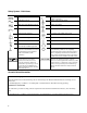
Error No. El E2 E3 E4 E5 E6 E7 Table 3-3. Power-On Selftest Errors Failed Test Error Display No. Front Panel RAM E8 SEC RAM Front Panel ROM checksum E9 SEC ROM EEPROM E10 SEC 5V Display FP RAM FP ROM EE CHKSUM PRI XRAM PRI IRAM PRI ROM GPIB Primary external RAM Primary internal RAM Primary ROM checksum GPIB R/W to serial poll Ell TEMP E12 DACS Failed Test Secondary RAM Secondary ROM checksum Secondary 5 V ADC reading Secondary ambient thermistor reading Secondary VDAC/IDAC readback Checksum Errors.
4 User Connections Rear Panel Connections Make application load connections to the output terminals or bus bars, analog connector, and digital connector as shown on the rear-panel drawing for your model power supply. Make controller connections (GPIB and serial link) as shown in Figure 4-6 at the end of this chapter. Load Wire Selection Fire Hazard To satisfy safety requirements, load wires must be large enough not to overheat when carrying the maximum short-circuit current of the power supply.
Note It is good engineering practice to twist and shield all signal wires to and from the analog and digital connectors Digital Connector This connector, which is on the rear panel, is for connecting fault/inhibit, digital I/O, or relay link signals. The connector accepts wires sizes from AWG 22 to AWG 12. Insert Wires ô Tighten Screws 1 Pin No.
Output Safety Cover ô Analog Connector í– Output Bus Bar ÷ – Local Sense Terminal û + Local Sense Terminal ø+ Output Bus Bar ù Signal Common î Local Sense Jumpers ü Rear Knockouts ê Bottom Knockout Insert screwdriver blade in slot and pry out Bend along joint and break off WARNING DO NOT LEAVE UNCOVERED HOLES IN OUTPUT COVER. IF TOO MANY KNOCKOUTS HAVE BEEN REMOVED, INSTALL A NEW COVER. Figure 4-3.
Local Voltage Sensing Your power supply was shipped set up for local sensing. This means that the unit will sense and regulate its output at the output terminals, not at the load. Since local sensing does not compensate for voltage drops across screw terminals, bus bars, or load leads, local sensing should only be used in applications that require low output current or where load regulation is not critical.
Note The signal ground binding post on the rear panel is a convenient place to ground the sense shield. OVP Considerations The OVP circuit senses the voltage near the output terminals and not at the sense terminals. Depending on the voltage drop between the output terminals and the load, the voltage sensed by the OVP circuit can be significantly higher than actually being regulated at the load. You must program the OVP trip high enough to compensate for the expected higher voltage at the output terminals.
Load Connection ôLoad íAnalog Connector Connect for remote sensing (optional) Connect for local sensing (default) Figure 4-5. Single Load Connection (Remote Sensing Optional) Connecting One Power supply To Multiple Loads Figure 4-6 shows how to connect a single power supply to more than one load. When connecting multiple loads to the power supply with local sensing, connect each load to the output bus bars with separate connecting wires.
Analog Connector ô Slave Unit í Master Unit ÷Program only the master. Set slave output and OVP slightly higher than the master to ensure that slave stays in CC mode û Load ø Load Connection Connect for optional remote sensing Only local sensing permitted Figure 4-7. Auto-Parallel Connection (Remote Sensing Optional) Auto-Parallel Programming. Program only the first ("master") unit in the series; the "slave" units automatically track the master’s output.
Load Connection ô Analog Connector ÷ Program each unit for full load current and 1/2 the load voltage í Load Connect for remote sensing (optional) WARNING FLOATING VOLTAGES MUST NOT EXCEED ±240 VDC NO OUTPUT TERMINAL MAY BE MORE THAN 240 V FROM CHASSIS GROUND. Figure 4-8. Series Connection (Remote Sensing Optional) External Voltage Control The setup shown in Figure 4-9 allows an external dc voltage to program the power supply output.
Programming. Note from Figure 4-1 that you have three options for programming the current. You can use a voltage source that is positive, negative, or floating with respect to Common P. Do not exceed ±15 V with respect to Common P. Make certain that the common connection for your voltage programming source is isolated from the load. Failure to do this may cause damage to the power supply.
ô í ÷ û ø ù A B 1. 2. 3. From 1 to 16 direct supplies may be connected to 1 controller GPIB interface. Tighten connector thumbscrews by hand. Do not use a screwdriver. Do not stack more than 3 connectors on a GPIB receptacle. GPIB cable (see Accessories in Chapter 1) From 1 to 15 linked supplies may be connected to 1 direct unit. Either receptacle (Jl or J2) may be used as an input or an output. Serial Link Cable (see Accessories in Chapter 1), 2 meters. 1 is supplied.
5 Front Panel Operation Introduction This chapter shows you how to operate the front panel. It is assumed that you are familiar with the turn-on checkout procedure in Chapter 3. That chapter describes how to perform basic power supply functions from the control panel. operations that you can perform are: ■ ■ ■ ■ ■ ■ ■ ■ ■ ■ Enabling or disabling the power supply output. Setting the output voltage and current. Monitoring the output voltage and current. Setting the overvoltage protection (OVP) trip point.
Figure 5-1. Front Panel Controls and Indicators Control or Indicator Table 5-1. Front Panel Controls and Indicators (See Figure 5-1) Function or Indication Display VOLTS AMPS CV CC Unr Dis OCP Prot Err Cal Shift Rmt Addr SRQ Shows present output voltage of the power supply. Shows present output current of the power supply. Status Annunciators The power supply is in constant-voltage mode. The power supply is in constant-current mode. The power supply output is unregulated (output is neither CV or CC).
Table 5-1. Front Panel Controls and Indicators (continued) í SYSTEM Keys When the power supply is under remote control, press to enable local operation. This control can be defeated by a lock-out command over the GPIB Press to display the power supply’s GPIB address. You can change the address with the ENTRY keys Use to display error codes generated during remote operation. (Select by pressing .) Use to restore a previously saved power supply state.
Programming The Output Important These instructions show how to program a single power supply. There are special considerations when you have two or more supplies connected in series or in autoparallel. See "Chapter 4 - User Connections and Considerations". The power supply accepts values directly in volts and amperes. Values will be rounded off to the nearest multiple of the output resolution (see “Programming Resolution" in Table A-2).
Setting the OVP Level. Assuming that you have programmed the power supply for 45 volts, you can set the OVP level to 48 volts as follows: Press . The display will change from meter mode to indicate 0V, followed by the present OVP value. Press . ■ The display will return to the meter mode and indicate the output (45.00 volts). ■ Press again. The display will now indicate 0V 48.00. ■ Press to return to the meter mode. ■ ■ Checking OVP Operation.
Programming Overcurrent Protection When enabled, overcurrent protection removes the power supply output whenever it goes into CC operation. This prevents the unit from indefinitely uniting the full programmed current to the load. . The OCP annunciator will light and power Setting The OCP Protection. To activate overcurrent protection, press supply will continue to operate normally until it is forced into CC operation. If that occurs, the OCP circuit will trip and the power supply will remove its output.
Saving and Recalling Operating States You can save programming time by storing up to 5 operating states in nonvolatile memory. The front panel programming parameters that are saved are: ■ Output voltage, Output current, *OVP voltage, ■ OCP state (on or off), Output state (enabled or disabled). Note More power supply parameters are saved in remote operation. See Chapter 7. As an example, set up the following state: ■ Voltage = 45 V Current = 5 A OVP voltage = 48 V.
1. As a stand-alone unit (the only unit at the address). It has a primary address in the range of 0 to 30. For example: 5 or 7. 2. As the direct unit in a serial link. It is the only unit connected directly to the GPIB bus. The primary address is unique and can be from 0 to 30. It is entered as an integer followed by a decimal separator. The secondary address always is 0, which may be added after the primary address. If the secondary address is omitted, it is assumed to be 0. For example: 5.0 or 7. 3.
6 Remote Programming Prerequisites for Remote Programming This organization of this guide assumes that you know or can learn the following information: 1. 2. 3. 4. 5. 6. How to program in your controller language (Agilent BASIC, QUICKBASIC, C, etc.). The basics of the GPIB (IEEE 488). How to program I/O statements for an IEEE 488 bus instrument. From a programming aspect, the power supply is simply a bus instrument. How to format ASCII statements within you I/O programming statements.
GPIB Capabilities of the Power supply All power supply functions except for setting the GPIB address are programmable over the IEEE 488 bus (also known as the General Purpose Interface Bus or "GPIB"). The IEEE 488.1 capabilities of the power supply are listed in the Supplemental Characteristics in Table A-2. The power supply operates from a GPIB address that is set from the front panel (see System Considerations at the end of this chapter).
Subsystem Commands. Subsystem commands (see Figure 6-1) perform specific power supply functions. They are organized into an inverted tree structure with the "root" at the top. Some are single commands while others are grouped under other subsystems. Figure 6-1. Partial Command Tree Traversing the Command Tree Figure 6-1 shows a portion of the subsystem command tree (you can see the complete tree in Figure 7-2). Note the location of the ROOT node at the top of the tree.
The optional header SOURCE precedes the current, digital, and voltage subsystems. This effectively makes :CURRENT, :DIGITAL, and :VOLTAGE root-level commands. Moving Among Subsystems In order to combine commands from different subsystems, you need to be able to restore the active path to the root. You do this with the root specifier (:).
Types of SCPI Messages There are two types of SCPI messages, program and response. • A program message consists of one or more properly formatted SCPI commands sent from the controller to the power supply. The message, which may be sent at any time, requests the power supply to perform some action. • A response message consists of data in a specific SCPI format sent from the power supply to the controller. The power supply sends the message only when commanded by a special program message called a "query.
Headers. Headers (which are sometimes known as "keywords") are instructions recognized by the power supply interface. Headers may be either in the long form or the short form. Long Form The header is completely spelled out, such as VOLTAGE STATUS DELAY. Short Form The header has only the first three or four letters, such as VOLT STAT DEL. Short form headers are constructed according to the following rules: • If the header consists of four or fewer letters, use all the letters.
SCPI Data Formats All data programmed to or returned from the power supply is ASCII. The data may be numerical or character string. Numerical Data Table 6-1 and Table 6-2 summarize the numerical formats. Symbol Class Current Amplitude Time Table 6-1. Numerical Data Formats Data Form Talking Formats Digits with an implied decimal point assumed at the right of the least-significant digit. Examples: 273 0273 Digits with an explicit decimal point. Example: 273. .
SCPI Command Completion SCPI commands sent to the power supply are processed either sequentially or in parallel. Sequential commands finish execution before a subsequent command begins. A parallel command can begin execution while a preexisting command is still executing (overlapping commands). Commands that affect trigger actions are among the parallel commands.
Programming Voltage and Current The following statements program both voltage and current and return the actual output from the sense terminals: OUTP OFF VOLT 45;CURR 25 VOLT?;CURR? OUTP ON MEAS:VOLT?;MEAS:CURR? Disable the output. Program the voltage and current. Read back the programmed levels. Enable the output. Read back the outputs from the sense terminals.
You can remotely save and recall operating states. See *SAV and *RCL in "Chapter 7 - Language Dictionary" for the parameters that are saved and recalled. Note When you turn the power supply on, it automatically retrieves the state stored in location 0. When a power supply is delivered, this location contains the factory defaults (see *RST in Chapter 7). OUTP OFF;VOLT:LEV 65;PROT 68 CURR:LEV 33;PROT:STAT ON *SAV 2 *RCL 2 Program a desired operating state. Save this state to location 2.
Note The last query string can be handled without difficulty. However, should you request too many queries, the system may return a "Query DEADLOCKED” error (-430). In that case, break the long string into smaller parts. Programming the Digital I/O Port Digital control ports 1 and 2 are TTL outputs that can be programmed either high or low. Control port 3 can be programmed to be either a TTL input or a TTL output.
Press Display returns to meter mode If you try to enter a forbidden number, ADDR ERROR is displayed.
DOS Drivers Types of Drivers The Agilent 82335A and National Instruments GPIB are two popular DOS drivers. Each is briefly described here. See the software documentation supplied with the driver for more details. Agilent 82335A Driver. For GW-BASIC programming, the GPIB library is implemented as a series of subroutine calls. To access these subroutines, your application program must include the header file SETUP.BAS, which is part of the DOS driver software. SETUP.
Programming Some Power supply Functions SAMPLE FOR POWER SUPPLY AT STAND-ALONE ADDRESS 6. SEQUENCE SETS UP CV MODE OPERATION, FORCES UNIT TO SWITCH TO CC MODE, AND DETECTS AND REPORTS MODE CHANGE. ************************************************************************** HP Vectra PC Controller Using Agilent 82335A Interface ************************************************************************** 5 ‘ < --------------- Merge SETUP.BAS here -------------------- > 1000 MAX.ELEMENTS=2 : ACTUAL.
Programming Some Power supply Functions (continued) 1220 CALL IOENTER (PS,OEVENT) 1225 IF PCIB.ERR < > NOERR THEN ERROR PCIB.BASERR 1230 IF (OEVENT AND 1024) = 1024 THEN PRINT "Unit switched to CC mode.
Programming Some Power supply Functions (continued) 1130 1135 1140 1146 1150 1160 1165 1170 1175 1180 1186 1190 1195 1200 1205 1210 1215 1220 1225 1230 1235 1240 1245 1250 1255 1260 1265 2000 2005 2010 2015 1250 1255 1260 1265 2000 2005 2010 2015 2020 2100 2105 2110 2115 2120 3000 3005 3010 3015 3020 3025 60 ’Enable Status Byte OPER summary bit CODES$ = "*SRE 128" ‘ 'Arm trigger circuit and send trigger to power supply CODES$ = "INITIATE;TRIGGER" :GOSUB 2000 'Wait for unit to respond to trigger FOR I= 1 t
Programming Some Power supply Functions (continued) 3030 WHILE C< >O 3035 D$=MID$(OUTPUT$,I,C-I) 3040 OUTPUT(X)=VAL(D$) 3045 I=C+1 3050 C=INSTR(I,OUTPUT$,";") 3055 X=X+1 3060 WEND 3065 D$=RIGHT$(OUTPUT$,LEN(OUTPUT$)-(I-1)) 3070 OUTPUT(X)=VAL(D$) 3076 OUTPUT$=SPACE$(40) 3080 RETURN **************************************************************************************************** Controller Using Agilent BASIC **************************************************************************************************
SCPI Confirmed Commands1 This power supply conforms to Version 1990.0.
7 Language Dictionary Introduction This section gives the syntax and parameters for all the IEEE 488.2 SCPI commands and the Common commands used by the power supply. It is assumed that you are familiar with the material in Chapter 6 - "Remote Programming". That chapter explains the terms, symbols, and syntactical structures used here and gives an introduction to programming. You should also be familiar with Chapter 5 - "Front Panel Operation" in order to understand how the power supply functions.
Description Of Common Commands Figure 7-1 shows the common commands and queries. These commands are listed alphabetically in the dictionary. If a command has a corresponding query that simply returns the data or status specified by the command, then both command and query are included under the explanation for the command. If a query does not have a corresponding command or is functionally different from the command, then the query is listed separately.
*ESE Meaning and Type Event Status Enable Device Status Description This command programs the Standard Event Status Enable register bits. The programming determines which events of the Standard Event Status Event register (see *ESR?) are allowed to set the ESB (Event Summary Bit) of the Status Byte register. A "1" in the bit position enables the corresponding event.
*IDN? Meaning and Type Identification Query System Interface Description This query requests the power supply to identify itself. It returns a string composed of four fields separated by commas. Query Syntax Returned Parameters Example Related Commands *IDN? Field Information Agilent Technologies Manufacturer xxxxA 4-digit model number followed by a letter suffix nnnnA-nnnnn 10-character serial number or 0 .xx.xx Revision levels of firmware Agilent Technologies,6681,0,A.00.
*OPC? Meaning and Type Operation Complete Device Status Description This query causes the interface to place an ASCII "1" in the Output Queue when all pending operations are completed. Pending operations are as defined for the *OPC command. Unlike *OPC, *OPC? prevents processing of all subsequent commands. *OPC? is intended to be used at the end of a command line so that the application program can then monitor the bus for data until it receives the "1" from the power module Output Queue.
Command Syntax Parameters Example Query Syntax Returned Parameters Related Commands *PSC 0 | 1 | OFF | ON *PSC 0 *PSC 1 *PSC? 0 | 1 *ESE *SRE *PSC causes a write cycle to nonvolatile memory. If *PSC is programmed to 0, then the *ESE and *SRE commands also cause a write cycle to nonvolatile memory. The nonvolatile memory has a finite number of write cycles (see Table A-2, Supplementary Characteristics).
*RST Meaning and Type Reset Device State Description This command resets the power supply to a factory-defined state as defined below. *RST also forces an ABORt command. Command State CAL:STAT OFF OUTP[:STAT] OFF CURR[:LEV][:IMM] * OUTP:PROT:DEL * CURR[:LEV]:TRIG * OUTP:REL[:STAT] OFF CURR:PROT:STAT OFF OUTP:REL:POL NORM DIG:DATA 0 TRIG:SOUR BUS DISP[:WIND]:STAT ON VOLT[:LEV][:IMM] * DISP[:WIND]:MODE NORM VOLT[:LEV][:TRIG] * DISP[:WIND]:TEXT VOLT:PROT[:LEV] * INIT:CONT OFF * Model-dependent. See Table 7-1.
*SRE Meaning and Type Service Request Enable Device Interface Description This command sets the condition of the Service Request Enable Register. This register determines which bits from the Status Byte Register (see *STB for its bit configuration) are allowed to set the Master Status Summary (MSS) bit and the Request for Service (RQS) summary bit.
Query Syntax *STB? Returned Parameters Related Commands (None) (Register binary value) *TRG Meaning and Type Trigger Device Trigger Description This command generates a trigger when the trigger subsystem has BUS selected as its source. The command has the same affect as the Group Execute Trigger () command.
Description Of Subsystem Commands Figure 7-2 is a tree diagram of the subsystem commands. Commands followed by a question mark (?) take only the query form. Except as noted in the syntax descriptions, all other commands take both the command and query form. The commands are listed in alphabetical order and the commands within each subsystem are grouped alphabetically under the subsystem. Figure 7-2. Subsystem Commands Tree Diagram ABOR This command cancels any trigger actions presently in process.
Current Subsystem This subsystem programs the output current of the power supply. CURR CURR:TRIG These commands set the immediate current level or the pending triggered current level of the power supply. The immediate level is the current programmed for the output terminals. The pending triggered level is a stored current value that is transferred to the output terminals when a trigger occurs.
Digital Subsystem This subsystem programs the control port on the back of the power supply when it is configured for Digital I/O operation. DIG:DATA This command sets and reads the power supply digital control port when that port is configured for Digital I/O operation. Configuring of the port is done via an internal jumper (see Appendix F). The port has three signal pins and a digital ground pin. Pins 1 and 2 are output pins controlled by bits 0 and 1.
DISP:MODE Switches the display between its normal metering mode and a mode in which it displays text sent by the user. The command uses the character data format. Command Syntax Parameters *RST Value Examples Query Syntax Returned Parameters Related Commands DISPlay[:WINDow]:MODE NORMalITEXT NORMal | TEXT NORM DISP:MODE NORM DISPLAY:MODE NORMAL DISPLAY:WINDOW:MODE TEXT DISPlay[:WINDow]:MODE? NORMAL or TEXT DISP DISP:TEXT *RST DISP:TEXT Allows character strings to be sent to display.
Initiate Subsystem This subsystem enables the trigger system. INIT INIT:CONT When a trigger is enabled with this command, an event on a selected trigger source causes the specified trigging action to occur. If the trigger subsystem is not enabled, all trigger commands are ignored. If INIT:CONT is OFF, then INIT enables the trigger subsystem only for a single trigger action. The subsystem must be enabled prior to each subsequent trigger action.
Output Subsystem This subsystem controls the power supply’s voltage and current outputs and an optional output relay. OUTP This command enables or disables the power supply output. The state of a disabled output is a condition of zero output voltage and a model-dependent minimum source current (see Table 7-1). The query form returns the output state.
OUTP:REL This command is valid only if the power supply is configured for the optional relay connector. Programming ON closes the relay contacts; programming OFF opens them. The relay is controlled independently of the output state. If the power supply is supplying power to a load, that power will appear at the relay contacts during switching. If the power supply is not configured for the relay option, sending either relay command generates an error.
Status Operation Registers The bit configuration of all Status Operation registers is shown in the following table. See "Chapter 8 - Status Reporting" for more explanation of these registers. Bit Configuration of Operation Registers 11 10 9 8 7 6 5 4 3 2 1 0 Bit Position 15-12 NU NU CC NU CV NU NU WTG NU NU NU NU CAL Bit Name 2048 1024 512 256 128 64 32 16 8 4 2 1 Bit Weight CAL = Interface is computing new calibration constants; CC = The power module is in constant current mode.
STAT:OPER:NTR STAT:OPER:PTR These commands set or read the value of the Operation NTR (Negative-Transition) and PTR (Positive-Transition) registers. These registers serve as polarity filters between the Operation Enable and Operation Event registers to cause the following actions: • • • • When a bit in the Operation NTR register is set to 1, then a 1-to-0 transition of the corresponding bit in the Operation Condition register causes that bit in the Operation Event register to be set.
STAT:QUES:COND? This query returns the value of the Questionable Condition register. That is a read-only register which holds the real-time (unlatched) questionable status of the power supply. Query Syntax Parameters Examples Returned Parameters Related Commands STATus:QUEStionable:CONDition? (None) STAT:QUES:COND? STATUS:QUESTIONABLE:CONDITION? (Register value) (None) STAT:QUES:ENAB This command and its query set and read the value of the Questionable Enable register.
System Commands System commands query error messages and software versions, and program system language functions. SYST:ERR? This query returns the next error number followed by its corresponding error message string from the remote programming error queue. The queue is a FIFO (first-in, first-out) buffer that stores errors as they occur. As it is read, each error is removed from the queue. When all errors have been read, the query returns 0,NO ERROR.
Trigger Subsystem This subsystem controls remote triggering of the power supply. TRIG When the trigger subsystem is enabled, TRIG generates a trigger signal. The trigger will then: 1. 2. 3. Initiate a pending level change as specified by CURR[:LEV]:TRIG or VOLT[:LEV]:TRIG. Clear the WTG bit in the Status Operation Condition register. If INIT:CONT has been given, the trigger subsystem is immediately re-enabled for subsequent triggers. As soon as it is cleared, the WTG bit is again set to 1.
Command Syntax Parameters Default Suffix *RST Value Examples Query Syntax MAX Returned Parameters Related Commands [SOURce]:VOLTage[:LEVel][:IMMediate][AMPLitude] [SOURce][:VOLTage[:LEVel]:TRIGgered[:AMPLitude] Table 7-1 V Table 7-1 VOLT 200 MA VOLTAGE:LEVEL 200 MA VOLTAGE:LEVEL:IMMEDIATE:AMPLITUDE 2.
Command Summary This summary lists all power supply subsystem commands in alphabetical order, followed by all common commands in alphabetical order. See Table 7-1 for the command parameters accepted by the power supply.
Command Summary Command Parameters Subsystem Commands (none) ABOR (See Appendix A in the Operating Manual) CAL [suffix] [SOUR]:CURR[:LEV][:IMM][:AMPL] (none) |MIN|MAX [SOUR]:CURR[:LEV][:IMM][:AMPL]? [suffix] [SOUR]:CURR[:LEV]:TRIG[:AMPL] (none) |MIN|MAX [SOUR]:CURR[:LEV]:TRIG[:AMPL]? 0 |l | ON|OFF [SOUR]:CURR:PROT:STAT (none) (SOUR]:CURR:PROT:STAT? [SOUR]:DIG:DATA[:VAL] (none) [SOUR]:DIG:DATA[:VAL]? NORM|TEXT DISP[WIND]:MODE (none) DISP(WIND]:MODE? DISP[:WIND][:STAT] 0 |l | OFF|ON (none)
8 Status Reporting Power supply Status Structure Figure 8-1 shows the status register structure of the power supply. The Standard Event, Status Byte, and Service Request Enable registers and the Output Queue perform standard GPIB functions as defined in the IEEE 488.2 Standard Digital Interface for Programmable Instrumentation. The Operation Status and Questionable Status registers implement status functions specific to the power supply.
Bit Signal 0 CAL 5 8 WTG CV 10 CC Table 8-2. Bit Configurations of Status Registers Meaning Bit Signal Meaning Operation Status Group Standard Event Status Group The interface is computing new calibration constants. The interface is waiting for a trigger. The power module is in constant voltage mode. The power module is in constant current mode. 0 OPC Operation complete. 2 3 QYE DDE Query error. Device-dependent error. 4 5 7 EXE CME PON Execution error. Command error. Power on.
Questionable Status Group Register Functions The Questionable Status registers record signals that indicate abnormal operation of the power supply. As shown in Figure 8-1, the group consists of the same type of registers as the Status Operation group. The outputs of the Questionable Status group are logically-ORed into the QUES(tionable) summary bit (3) of the Status Byte register.
Status Byte Register This register summarizes the information from all other status groups as defined in the "IEEE 488.2 Standard Digital Interface for Programmable Instrumentation" standard. The bit configuration is shown in Table 8-1. The register can be read either by a serial poll or by *STB?. Both methods return the same data, except for bit 6. Sending *STB? returns MSS in bit 6, while poring the register returns RQS in bit 6.
Initial Conditions At Power On Status Registers When the power supply is turned on, a sequence of commands initializes the status registers. For the factory-default *RST power-on state, Table 8-4 shows the register states and corresponding power-on commands. Table 8-4.
Servicing an Operation Status Mode Event This example assumes you want a service request generated whenever the power supply switches to the CC (constant current) mode. From Figure 8-1, note that the required path is for a condition at bit 10 (CC) of the Operation Status register to set bit 6 (RQS) of the Status Byte register. The required register programming is shown in Table 8-5. Table 8-5.
A Specifications Specifications are performance parameters warranted over the specified temperature range. Supplemental Characteristics are not warranted but are descriptions of performance determined either by design or type testing. Table A-1. Performance Specifications for Agilent E4356A Parameter Value Output Ratings Voltage: 0 - 80 V (0 to 26A) Current: 0 - 30 A (0 to 70 V) (@ 0 to 45°C) Programming Accuracy Voltage: 0.04% + 80 mV Current: 0.
Table A-2. Supplemental Characteristics for Agilent E4356A Parameter Value Output Programming Range Voltage: 81.9 V Current: 30.71 A Overvoltage Protection: 96 V Typical Programming Resolution Voltage: 20 mV Current: 7.5 mA Overvoltage Protection: 150 mV Accuracy Overvoltage Protection (OVP): 1.5 V Analog Programming (VP): ( @ 25 °C ± 5 °C) ± 0.3% Analog Programming (IP): ± 7% Current Monitor (+IM): ± 7% Voltage: 0.02% + 2.5 mV Drift Temperature Stability (following a 30-minute warmup, change Current: 0.
Table A-2.
Safety Compliance RFI Suppression Dimensions Weight Table A-2. Supplemental Characteristics (continued) CSA 22.2 No.231,IEC 348 Complies with: Designed to comply with: UL 1244 Complies with: CISPR-ll, Group 1, Class B 425.5 mm (16.75 in) Width: Height (with removable feet): 145.1 mm (5.71 in) Depth (with safety cover): 640 mm (25.2 in) 27.7 kg (61 lb) Net: Shipping: 31.
B Calibration Introduction The power supply may be calibrated either from the front panel or from a controller over the GPIB. The procedures given here apply to all models. Important These instructions do not include verification procedures. If you need to perform verification as a prerequisite to or as part of your calibration procedure, see “Appendix B - Verification”. Equipment Required The equipment listed in Table B-1, or equivalent, is required for calibration. Equipment Voltmeter Table B-1.
Front Panel Calibration Eight shifted keys and the Entry keypad are used for calibration functions (see Chapter 5 for explanations of shifted keys and the Entry keypad). The following procedures assume you understand how to operate front panel keys. Entering the Calibration Values Follow the steps in Table B-2 for entering calibration values. Saving the Calibration Constants Storing calibration constants overwrites the existing ones in nonvolatile memory.
Table B-2. Typical Front Panel Calibration Procedure Action Enabling the Calibration Mode 1. Begin calibration by pressing . 2. Enter calibration password from Entry keypad. If password is correct the Cal annunciator will come on. If password is incorrect, an error occurs 2. Note: The initial (factory-default) password is the model number of the power supply, but it can be changed (see "Changing the Password"). Entering Voltage Calibration Values 1. Make certain the DVM is the only load on the power supply.
Recovering From Calibration Problems You can encounter serious calibration problems if you cannot determine a calibration password that has been changed or the power supply is severely out of calibration. There are jumpers inside the power supply that permit the calibration password to be defeated and allow the original factory calibration constants to be restored. These jumpers are explained in the Service Manual.
Calibration Language Dictionary The calibration commands are listed in alphabetical order. The format for each command follows that shown in Chapter 7. Calibration error messages that can occur during GPIB calibration are shown in Table B-3. CAL:CURR This command is used to calibrate the output current. The command enters current value that you obtain from an external meter. (If you are entering the current value, allow time for the DVM to stabilize.
CAL:STAT This command enables and disables the calibration mode. The calibration mode must be enabled before the power supply will accept any other calibration commands. The first parameter specifies the enabled or disabled state. The second parameter is the password. It is required if the calibration mode is being enabled and the existing password is not 0. If the second parameter is not entered or is incorrect, an error is generated and the calibration mode remains disabled.
BASIC Calibration Program The following program can be run on any controller operating under Agilent BASIC. The assumed power supply address is 5 and calibration password is 4356. If required, change these parameters in the appropriate statements. 10 ! Agilent BASIC Calibration Program 20 ! 30 DIM Resp$ [255],Err_msg$[255] 40 ! 50 Volt_cal: ! Voltage DAC calibration 60 Err_found=0 70 PRINT TABXY(5,10),"CONNECT INSTRUMENTS AS SHOWN IN FIG. A -1(1).
Figure B-2. BASIC Calibration Program (continued) Imon DAC and Current DAC calibration 480 Current_cal: ! 490 Err_found=0 500 PRINT TABXY(5,10),"CONNECT INSTRUMENTS AS SHOWN IN FIG. A -1(2).
C Verification Introduction This appendix provides operation verification test procedures. The tests do not check all the operating parameters, but verify that the power supply is performing properly. The required test equipment and acceptable test results are specified in tables at the end of this appendix. Note Performance Tests, which check all the specifications of the power supply, are given in the Service Manual.
Performing The Tests General Measurement Techniques Figure C-1 shows the setup for the tests. Be certain to use load leads of sufficient wire gauge to carry the output current (see Table 8-1). To avoid noise pickup, use coaxial cable or shielded pairs for the test leads. Programming the Power supply Appendix A lists the programming voltage and current ranges. Enter the appropriate values from the front panel.
Current Programming and Readback Accuracy This test verifies that the current programming and readback are within specification. Connect the appropriate current monitoring resistor (see Table C-1) as shown in Figure C-1(2). The accuracy of the resistor must be as specified in the table. Table C-3. Current Programming and Readback Accuracy Test Action Normal Result 1 Turn off the power supply and connect the current monitoring resistor as shown in Figure C-1(2).
D Error Messages Power supply Hardware Error Messages Front panel error messages resulting from selftest errors or runtime failures are described in “Chapter 3 - Turn-On Checkout”. Calibration Error Messages Front panel error messages resulting from calibration errors are described in Appendix B. System Error Messages System error messages are obtained remotely with the SYST:ERR? query or by pressing the front panel key. The error number is the value placed in the error queue.
Error Number -141 -144 -148 -150 -151 -158 -160 -161 -168 -220 -221 -222 -223 -240 -241 -310 -313 -330 -350 -400 -410 -420 -430 -440 Table D-1. Summary of System Error Messages (continued) Error String [Description/Explanation/Examples] Invalid character data [bad character, or unrecognized] Character data too long [maximum length is 12 characters] Character data not allowed [character data not accepted where positioned] String data error [generic string error] Invalid string data [e.g.
E Line Voltage Conversion SHOCK HAZARD. Hazardous voltage can remain inside the power supply even after it has been turned off. This procedure should only be done by qualified electronics service personnel. Line voltage conversion is accomplished by setting a line voltage select switch. Proceed as follows: 1. Turn off the ac power and disconnect the power cord from the power source. 2. Remove the four screws securing the carrying straps and dustcover. 3.
F Digital Port Functions Digital Connector A 4-pin connector and a quick-disconnect mating plug are provided for digital input and output signals (see Figure F-l for wiring connections, and Table A-2 for electrical characteristics). This digital port can be configured to provide either Fault/Inhibit or Digital I/O functions. Note Consistent with good engineering practice, twist and shield all signal wires to and from the digital connector. Figure F-1.
GPIB Figure F-2. Example of Inhibit Input In Figure F-3A, the FLT output is connected to a relay driver circuit that energizes a relay whenever a fault condition occurs in the power supply. The relay can be used to physically disconnect the output of the power supply from the load. The FLT output is generated by the logical ORing of the power supply’s Operation, Questionable, and Event status summary bits (see "Chapter 8 - Status Reporting” in the Programming Guide).
Changing The Port Configuration As shipped from the factory, the digital port is configured for FLT/INH operation. You can change the configuration of the port to operate as a general-purpose digital input/output port to control your custom circuitry as shown in Figure F-4. To change the port configuration, you must move a jumper on the GPIB board. Shock Hazard. Hazardous voltage can remain inside the power supply even after it has been turned off.
Digital I/O Operation The digital port can be configured (see Figure F-4) to provide a digital input/output to be used with custom digital interface circuits or relay circuits. Some examples are shown Figure F-5. See Figure F-1 for the pin assignments of the mating plug and Appendix A for the electrical characteristics of the port. See DIG:DATA[:VAL] in “Chapter 7 - Language Dictionary" for information on programming the port.
Figure F-6 shows how to connect your power supply to an Agilent 59510A or 59511A Relay Accessory when the digital port is configured for relay link operation. An error will be generated if you attempt to program the relay box without first configuring the digital port for relay link operation . For more information about programming the relay, refer to OUTP:REL[:STAT] in Chapter 7. For more information about the Relay Accessory, refer to its manual (see Table 1-4). Figure F-6.
G Compatibility Language Introduction This power supply is programatically compatible with the Agilent 603xA Series AutoRanging Power Supplies (ARPS). This means that you can program this power supply over the GPIB using the ARPS commands. Software that you have written for the autoranging power supplies can also be adapted to program this power supply. Note The Agilent E4356A Power supply’s serial link is not supported by ARPS commands. You can use only a GPIB primary address for the power supply.
Table G-1. ARPS Commands 1 ARPS Command Description These commands program output voltage. See Table 7-1 for the programming ranges of these commands. Initial condition: 0 V These commands program output current. See Table 7-1 for the programming ranges for these commands. Initial condition: 0 A These commands read voltage or current settings. VSET x VSET xV VSET xMV ISET x ISET xA ISET xMA VSET? ISET? VOLT? IOUT? OVP x OVP xV OVP xMV These commands measure and read output voltage or current.
1 ARPS Command RST HOLD OFF HOLD 0 HOLD ON HOLD 1 Table G-1. ARPS Commands (continued) Description This command resets the power supply if the output is disabled by the overvoltage, remote inhibit, or foldback protection circuits. The power supply resets to the parameters stored for the power-on state. Note that the settings can be changed while the unit is disabled.
Table G-1. ARPS Commands (continued) Description 1 ARPS Command Similar SCPI Command STAT:OPER:ENAB? STAT:QUES:ENAB? ESE UNMASK? This command reads which bits in the status register have been enabled as fault conditions. The decimal equivalent of the total bit weight of all enabled bits is returned. FAULT? This command reads which bits have been set in the fault register.
Index —<— , 51 , 51 , 51 , 51 , 51 , 51 —A— AARD, 51 accessories, 14 active header path, 47 airflow, 18 analog connector, 17 analog connector, 27 annunciators Addr, 38 AMPS, 38 Cal, 38 CC, 38 CV, 38 Dis, 38 Err, 38 OCP, 38 Prot, 38 Rmt, 38 Shift, 38 SRQ, 38 Unr, 38, 42 VOLTS, 38 Arps commands, 122 auto-parallel connections, 32 auto-parallel programming, 33 AWG wire size, 27 —B— battery charging, 29 —C— cables, 14 calibration equipment, 99 example, 105 GPIB, 102 password,
connector analog, 27 digital, 28 controller connections, 35 linked, 35 stand-alone, 35 conventions, 46 CRD, 51 current monitor resistor, 107 current programming, 41, 53 current sinking, 16 cv mode, 16, 42 Ouptut On/Off, 39 OV, 39 Prot Clear, 39 Protect, 39 Voltage, 39 fuse location, 25 replacing, 25 —G— ground, earth, 13 guide, user’s, 13 —D— damage, 17 description, 15 detecting SRQ events, 54 DFI descrete fault indicator, 90 digital connector, 17, 28, 115 digital I/O, 28 digital I/O programming, 55 digi
load, inductive, 29 local voltage sensing, 30 location, 18 —M— master unit, 32 message terminator, 50 message unit separator, 50 moving among subsystems, 48 multiple load connections, 32 multipliers, 51 —N— NTR filter, 92 numerical data format, 51 —Q— —O— OCP checking, 42 clearing, 42 programming, 42, 53 setting, 42 operating curve, 40 operation status group, 87 optional headers effect, 47 options, 14 ouptut queue, 90 OUT 0, 118 OUT 1, 118 output rating, 16 output connections, 29 output impedance, 98 ou
data format, 51 header path, 47 message structure, 49 message types, 49 message unit, 49 multiple commands, 47 non-conformance, 62 program message, 49 queries, 48 references, 45 response message, 49 subsystem commands, 46, 72 secondary address, 44, 55 selftest errors, 25 serial cable, 17 series connections, 33 service request, 91 programming, 92 service request enable register, 90 servicing status events, 92 shift function, 37, 38 single load connections, 31 slave unit, 32 specifications, 95 SRQ events dete
voltage programming, 40, 53 voltage sensing, local, 30 voltage sensing, remote, 30 VP, 27 VXIplug&play, 13, 20 —W— warranty, 2 wire capacity, 27 wire resistance, 27 wire size, 27 writing to the display, 54 Index 127
Agilent Sales and Support Offices For more information, call your local Agilent sales office listed in your telephone directory or an Agilent regional office listed below for location of your nearest sales/support office. United States of America: Agilent Technologies Company Test and Measurement Organization 5301 Stevens Creek Blvd Bldg 51L-5C Santa Clara, CA 95052-8059 (800) 452 4844 Asia Pacific: Agilent Technologies Asia Pacific Ltd.
Manual Updates The following updates have been made to this manual since the print revision indicated on the title page. 3/01/00 All references to HP have been changed to Agilent. All references to HP-IB have been changed to GPIB.