
User's Manual

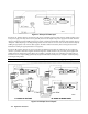
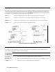

Table Of Contents
- TABLE OF CONTENTS
- Safety Summary
- Safety Symbols
- Acoustic Noise Info
- Declaration Page
- Printing History
- GENERAL INFORMATION
- INSTALLATION
- TURN-ON CHECKOUT
- USER CONNECTIONS
- FRONT PANEL OPERATION
- REMOTE PROGRAMMING
- LANGUAGE DICTIONARY
- STATUS REPORTING
- SPECIFICATIONS
- CALIBRATION
- VERIFICATION
- ERROR MESSAGES
- LINE VOLTAGE CONVERSION
- DIGITAL PORT FUNCTIONS
- COMPATIBILITY LANGUAGE
- INDEX
- Agilent Sales and Support Office
- Manual Updates
Digital Port Functions 117
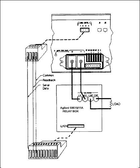
Figure F-6 shows how to connect your power supply to an Agilent 59510A or 59511A Relay Accessory when the digital
port is configured for relay link operation. An error will be generated if you attempt to program the relay box without first
configuring the digital port for relay link operation. For more information about programming the relay, refer to
OUTP:REL[:STAT] in Chapter 7. For more information about the Relay Accessory, refer to its manual (see Table 1-4).
Figure F-6. Relay Link Connections