
User`s guide

3- 24 Keysight B1500A User’s Guide, Edition 14
Installation
Installing Accessories
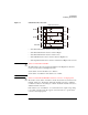
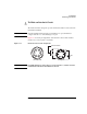
2. Fix the SCUU inside or outside the shielding box. The SCUU must be fixed to
the best position for accessing its connectors. Keysight N1301A-110 Magnetic
Stand will be useful for fixing the SCUU.
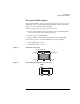
3. Attach the other end of the SCUU cable to the B1500A rear panel connectors for
the MFCMU in the slot N and two SMUs in the slots N-1 and N-2 (N: integer, 3
to 10).
Connection will be easy by bringing the control connectors together before
bringing the BNC connectors.
4. Fix the GSWU in the shielding box. The GSWU must be fixed to the best
position for accessing its connectors.
5. Connect the GSWU cable (Keysight N1301A-201/202) between the SCUU and
the GSWU.
If the SCUU is fixed outside the shielding box, pass the GSWU cable through
the cable hole of the 16495K.
6. Adjust the cable length in the shielding box, and catch in the cables by using the
cover of the 16495K.
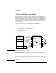
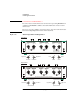
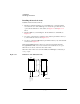
7. Connect the proper cables from Force1/CMUH and Force2/CMUL to the 16495
connector plates or the DUT interface. See Figure 3-5.
For the Kelvin connections, also connect the proper cables from Sense1 and
Sense2 to the 16495 connector plates or the DUT interface.
8. Connect the wires (furnished, 2 ea.) to the GSWU.
9. Connect one of the wires to the Guard terminal extended from CMUH of SCUU.
Then the wire should contact the Guard terminal as close to the device as
possible.
10. Connect another one to the Guard terminal extended from CMUL of SCUU.
Then the wire should contact the Guard terminal as close to the device as
possible.
NOTE
About SCUU output cables
To perform capacitance measurements accurately, the cable length between DUT
and the SCUU output must be as short as possible.