
Technical data


2-14 Agilent B2900A Configuration and Connection Guide, Edition 1
B2900A Accessories
Other I/F and Interlock
• 5 V power supply pin:
Limited to 600 mA, solid state fuse protected
• Safety interlock pin:
One active high pin and one active low pin. Activation of both pin enables output
voltage > 42 V.
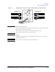
2.4.3 Installing the Interlock Circuit
The B2900A cannot apply high voltage over ± 42 V when the Digital I/O interlock
terminal is open. To perform high voltage measurement, the B2900 interlock terminal must
be connected to the interlock circuit installed in the measurement environment such as the
shielding box. The interlock circuit is important and necessary to prevent electrical shock
when an user touches the measurement terminals.
Pin 16 and 24 are reserved for the interlock function. If the terminals are open, the
instrument output is limited to ± 42 V. Be sure to connect the terminals to the Agilent
16442B test fixture or another DUT interface before performing measurement. If you do
not use the 16442B, you need to install an interlock circuit as shown in Figure 2-7.
Please refer to the “Installing the Interlock Circuit” in the Agilent B2900A Series User's
Guide for the details.
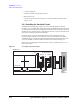
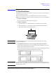
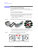
Figure 2-7 An example of Interlock Circuit
Mechanical switches
Shielding box
LED
Access door
D-sub connector
Interlock circuit
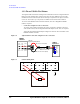
B2900
Digital I/O
15, 19
14
17, 18
16
24, 25
Dsub cable
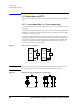
15, 19
22, 23
16, 17
24
14
Negative
Positive
or