
Technical data
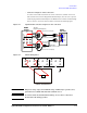

3- 10 Agilent B2900A Configuration and Connection Guide, Edition 1
Connection
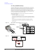
Connection with Test Fixture
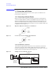
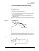
• Connection example for three terminals device by 2 channels of SMU
To connect to the 16442B test fixture for three terminals device by 2 channels of SMU,
two sets of N1294A-001 banana to triaxial adapter for 2 wire (non-kelvin) connection
and four 16494A triaxial cables are required.
Attach the banana to triaxial adapter to the B2900A source/measure terminals.
Connect the triaxial cables between the adapter and the 16442B as shown in the
following figure.
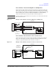
Figure 3-16 Agilent 16442B connection example for three terminals device by 2 SMUs
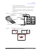
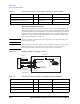
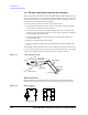
Figure 3-17 16442B Wiring Panel (BJT (NPN) by 2 channels of SMU)
CAUTION Maximum voltage and current
The test fixture and adapters must be used under the following limitations to prevent damage to them.
Agilent N1294A-001 and 002 Banana to Triax adapter:
±250 V maximum, ±200 V maximum for connecting 16442B test fixture.
Agilent 16442B Test Fixture: ±200 V, 1 A maximum for SMU input
N1294A-001 Adapter
for the 2-wire connections
16494A Triaxial Cable
16442B Test Fixture
1
2
SMU
3
4
5
6
PGU
VSU
1 2
1 2
VMU
1 2
GNDU
Interlock
Low Force (Ch 1) to SMU 2
High Force (Ch 1) to SMU 1
N1294A-011 or 012
Interlock cable for 16442B
1
2
3
Channel 1
Channel 2
Low Force (Ch 2) to SMU 4
High Force (Ch 2) to SMU 3
SMU(±200V= 1A Max)
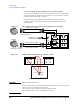
Sense Force
Guard Guard
1
Sense Force
Guard Guard
2
Sense Force
Guard Guard
3 (Selected)
Connections for BJT (NPN)
EmitterCollector
Base