Agilent 83491/2/3A Clock Recovery Modules User’s Guide
© Copyright 2000 Agilent Technologies All Rights Reserved. Reproduction, adaptation, or translation without prior written permission is prohibited, except as allowed under copyright laws. Agilent Part No. 83491-90013 Printed in USA February 2000 Agilent Technologies Lightwave Division 1400 Fountaingrove Parkway Santa Rosa, CA 95403-1799, USA (707) 577-1400 Notice. The information contained in this document is subject to change without notice.
General Safety Considerations General Safety Considerations This product has been designed and tested in accordance with IEC Publication 61010-1, Safety Requirements for Electrical Equipment for Measurement, Control and Laboratory Use, and has been supplied in a safe condition. The instruction documentation contains information and warnings that must be followed by the user to ensure safe operation and to maintain the product in a safe condition.
General Safety Considerations Technologies part number 2110-0449. • For 220/240V operation, use an IEC 127 5×20 mm, 0.16 A, 250 V, Agilent Technologies part number 2110-0448. CAUTION Before switching on this instrument, make sure that the line voltage selector switch is set to the line voltage of the power supply and the correct fuse is installed. Assure the supply voltage is in the specified range.
Contents General Safety Considerations iii 1 Installation Installation 1-2 2 Operation Agilent 83491/2/3A Modules—At a Glance 2-2 Front-Panel Features 2-4 Block Diagrams 2-7 To Display a Signal 2-8 To Compensate for Module Insertion Loss 2-9 Using Probes with an Agilent 83491A 2-10 3 Specifications and Regulatory Information Agilent 83491A Specifications 3-3 Agilent 83492A Specifications 3-4 Agilent 83493A Specifications 3-6 Agilent 83491/2/3A Operating Specifications 3-7 Declaration of Conformity 3-8 4 Re
1 To install the module 1-3 To connect cables to an Agilent 83492A Installation 1-7
Installation Installation Installation Agilent 83491/2/3A modules require that firmware revision A.06.25 or later be installed in the Agilent 83480A. If you wish to install the module in an Agilent 54750A digitizing oscilloscope, you must first install the Agilent 83480K communications firmware upgrade kit. To check the Agilent 83480A’s firmware revision code 1 Press the Utility key and then the System config softkey. 2 The firmware revision number is listed under the Frame section of the display.
Installation Installation To install the module 1 Verify that all system components ordered have arrived by comparing the shipping forms to the original purchase order. Inspect all shipping containers.
Installation Installation Figure 1-2. Position of modules in the mainframe 3 Clean all optical interfaces as described in “Cleaning Connections for Accurate Measurements” on page 4-10, before making measurements. 4 Perform the following steps if you’re installing an Agilent 83492/3A module: a Unscrew and remove the fiber-optic adapter that is located on the optical module’s front-panel optical input connector.
Installation Installation Figure 1-3. The adapter cable CAUTION Agilent 83491A Modules: Maximum safe signal input level is ±5V. The input circuits can also be damaged by electrostatic discharge (ESD). Before connecting any coaxial cable to the connectors, momentarily short the center and outer conductors of the cable together. Avoid touching the front-panel input connectors without first touching the frame of the instrument.
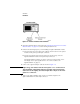
Installation Installation Figure 1-4. Front-panel lights 9 Confirm that the Unlocked light is off. 10 Observe the Clock and Data outputs on an oscilloscope. Waveforms should be present. The instrument is now ready for you to begin making measurements.
Installation Installation To connect cables to an Agilent 83492A On Agilent 83492A modules, the front-panel fiber-optic connectors reverse input and output roles depending on the wavelength of the signal. Signals in the 750 nm to 860 nm wavelength range are input to the left connector and output from the right connector. Signals in the 1000 nm to 1600 nm wavelength range are input to the right connector and output from the left connector. Figure 1-5.
2 Agilent 83491/2/3A Modules—At a Glance 2-2 Front-Panel Features 2-4 Block Diagrams 2-7 To Display a Signal 2-8 To Compensate for Module Insertion Loss 2-9 Using Probes with an Agilent 83491A 2-10 To compensate for a passive probe 2-11 To compensate an Agilent 54701A active probe To compensate for other devices 2-12 Operation 2-11
Operation Agilent 83491/2/3A Modules—At a Glance Agilent 83491/2/3A Modules—At a Glance The Agilent 83491/2/3A are designed to operate in an Agilent 83480A digital communications analyzer. These modules recover clock and data information at standard telecom and datacom rates. The resulting trigger signal is made available to the Agilent 83480A mainframe via a connector located on the module’s rear-panel.
Operation Agilent 83491/2/3A Modules—At a Glance WARNING Light energy can radiate from the front panel OUTPUT connectors on Agilent 83492A and 83493A modules. The light emitted from these connectors is the slightly attenuated light that is input to the frontpanel INPUT connector.
Operation Front-Panel Features Front-Panel Features Figure 2-2. Agilent 83491/2/3A front panels SELECT key Pressing this key changes the modulation rate of the input signal. The recovered and retimed clock trigger is sent to the mainframe. The Trigger On Data selection is a bypass mode where the data stream directly triggers the mainframe. Refer to “Block Diagrams” on page 2-7 to view a schematic of the normal and bypass paths.
Operation Front-Panel Features Green and red data-rate lights The data-rate indicator lights change color between red and green to show which data rate is selected. A red light does not indicate a problem. A red light shows that the adjacent red data rate label is selected. A green light shows that the adjacent green data rate label is selected. Repeatedly pressing the SELECT key cycles through the selections in one color before switching to the opposite color.
Operation Front-Panel Features Multimode and single-mode connections Agilent 83492A modules use multimode fiber. Connecting the output to the Optical INPUT connector on Agilent 83481/2/5 single-mode modules results in large reflections and insertion loss. Agilent 83493A modules use 9/125 µm single-mode fiber. Connecting multimode fiber to the Optical Input connector results in large reflections and insertion loss.
Operation Block Diagrams Block Diagrams Figure 2-3. Agilent 83491A Block Diagram Figure 2-4.
Operation To Display a Signal To Display a Signal 1 Install the module as described in “To install the module” on page 1-3. Be sure to connect all of the cables as described in the procedure. 2 Repeatedly press the SELECT key on the clock recovery module until the frontpanel light indicates the proper data rate of the signal. Green and red data-rate lights The data-rate indicator lights change color between red and green to show which data rate is selected. A red light does not indicate a problem.
Operation To Compensate for Module Insertion Loss To Compensate for Module Insertion Loss The following steps allow you to enter an offset to compensate for the insertion loss of the clock recovery module. This provides accurate amplitude measurements at the input to the clock recovery module. 1 Disconnect the cable from the clock recovery module’s Input connector. 2 Measure the signal using a power meter. You can use either the Agilent 83480A’s built-in power meter or an external power meter.
Operation Using Probes with an Agilent 83491A Using Probes with an Agilent 83491A You can use external passive and active probes with the Agilent 83491A electrical clock recovery module. The procedures in this section generate vertical scale factors. These factors are applied to the calibration of the reference receiver module’s electrical channel. When selecting a probe, keep in mind that the input impedance of the Agilent 83491A is 50Ω.
Operation Using Probes with an Agilent 83491A To compensate for a passive probe 1 Connect the probe to the Input connector on the Agilent 83491A clock recovery module. 2 Attach the probe tip to the CAL hook that is located near the floppy disk drive. 3 Press the reference receiver module’s front-panel channel SETUP key. 4 Press Calibrate and then Calibrate probe. To compensate an Agilent 54701A active probe 1 Connect the Agilent 83491A output to the electrical measurement channel input.
Operation Using Probes with an Agilent 83491A To compensate for other devices The information in this section applies to both optical and electrical measurements. Since the mainframe’s CAL signal is a voltage source, it cannot be used to calibrate to the probe tip when the units are set to Ampere, Watt, or Unknown. Instead, set the external gain and external offset to compensate for the actual characteristics of the device.
3 Agilent 83491A Specifications 3-3 Agilent 83492A Specifications 3-4 Agilent 83493A Specifications 3-6 Agilent 83491/2/3A Operating Specifications Declaration of Conformity 3-8 3-7 Specifications and Regulatory Information
Specifications and Regulatory Information Specifications and Regulatory Information Specifications and Regulatory Information This chapter lists specifications and characteristics of the Agilent 83491/2/3A. Specifications apply over the temperature range +15°C to +35°C (unless otherwise noted) after the instrument’s temperature has been stabilized after 60 minutes of continuous operation. Specifications Specifications described warranted performance.
Specifications and Regulatory Information Agilent 83491A Specifications Agilent 83491A Specifications Table 3-1. Agilent 83491A Specifications Clock recovery rates (NRZ coding) 155.52 Mb/s 622.08 Mb/s 1062.50 Mb/s 1250 Mb/s 2125.00 Mb/s 2488.32 Mb/s 2500.00 Mb/s ±0.1% ±0.1% ±0.1% ±0.1% ±0.1% ±0.1% ±0.
Specifications and Regulatory Information Agilent 83492A Specifications Agilent 83492A Specifications Table 3-2. Agilent 83492A Specifications (1 of 2) Wavelength range (characteristic) 750 nm to 860 nm and 1000 nm to 1600 nm Optical INPUT and OUTPUT fiber (characteristic) 62.5/125 multimode Optical insertion loss (through path) a 750 nm to 860 nm 1000 nm to 1600 nm ≤ 5.0 dB ≤ 5.0 dB Optical return loss b ≥ 28 dB Clock recovery rates (NRZ coding) 155.52 Mb/s 622.08 Mb/s 1062.
Specifications and Regulatory Information Agilent 83492A Specifications Table 3-2. Agilent 83492A Specifications (2 of 2) DATA and CLOCK electrical return loss 50 MHz through 2000 MHz (characteristic) 2000 MHz through 2500 MHz (characteristic) ≥ 10 dB ≥ 6 dB a. Minimum loss in 850 nm window. b. Single-mode backreflection tested with FC/PC adapter and single-mode fiber. Optical output terminated with > 33 dB return loss. Return loss with fully filled 62.5 µm core multimode fiber may be slightly lower. c.
Specifications and Regulatory Information Agilent 83493A Specifications Agilent 83493A Specifications Table 3-3. Agilent 83493A Specifications Wavelength range (characteristic) 1000 nm to 1600 nm Optical INPUT fiber (characteristic) 9/125 single mode Optical insertion loss (through path) ≤ 1.5 dB Optical return loss a ≥ 28 dB Clock recovery rates (NRZ coding) 155.52 Mb/s 622.08 Mb/s 1250 Mb/s 2488.32 Mb/s 2500.00 Mb/s ±0.1% ±0.1% ±0.1% ±0.1% ±0.
Specifications and Regulatory Information Agilent 83491/2/3A Operating Specifications Agilent 83491/2/3A Operating Specifications Table 3-4. Agilent 83491/2/3A Operating Specifications Use Indoor Temperature Operating Non-operating 0°C to +55°C –40°C to +70°C Altitude Operating Non-operating 4600 m (15,000 ft) 15,300 m (50,000 ft) Humidity Operating Non-operating up to 90% relative humidity at <35°C up to 90% relative humidity at <35°C Net weight approximately 1.2 kg (2.6 lb.
Specifications and Regulatory Information Declaration of Conformity Declaration of Conformity 3-8
4 Front-Panel Optical Adapters 4-2 In Case of Difficulty 4-3 Error Messages 4-5 Electrostatic Discharge Information 4-8 Cleaning Connections for Accurate Measurements Returning the Instrument for Service 4-20 Agilent Technologies Service Offices 4-23 Reference 4-10
Reference Front-Panel Optical Adapters Front-Panel Optical Adapters Front Panel Fiber-Optic Adapter Description Agilent Part Number Diamond HMS-10 81000AI FC/PCa 81000FI D4 81000GI SC 81000KI DIN 81000SI ST 81000VI Biconic 81000WI Dust Covers FC connector 1005-0594 Diamond HMS-10 connector 1005-0593 DIN connector 1005-0595 ST connector 1005-0596 SC connector 1005-0597 a. The FC/PC adapter is the standard adapter supplied with the instrument.
Reference In Case of Difficulty In Case of Difficulty This section provides a list of suggestions for you to follow if the plug-in module fails to operate. A list of messages that may be displayed is also included in this chapter. Before calling Agilent Technologies or returning the unit for service, a few minutes spent performing some simple checks may save waiting for your instrument to be repaired.
Reference In Case of Difficulty peared. Are all the settings correct? Can the problem be reproduced? ❒ Are the connectors clean? See “Cleaning Connections for Accurate Measurements” on page 4-10 for more information. ❒ Perform the following procedures: 1 Make sure that the instrument is ready to acquire data by pressing Run. 2 Find any signals on the channel inputs by pressing Autoscale. 3 See if any signals are present at the channel inputs by pressing Trigger, Sweep, Freerun.
Reference Error Messages Error Messages The following error messages are for the plug-in module. Typically, the error messages indicate there is a problem with either the plug-in or the mainframe. This section explains what the messages mean and offers a few suggestions that might help resolve the error condition. If the suggestions do not eliminate the error message, then additional troubleshooting is required that is beyond the scope of this book.
Reference Busy timeout occurred with plug-in_:Try reinstalling plug-in Busy timeout occurred with plug-in_:Try reinstalling plug-in The mainframe is having trouble communicating with the plug-in module. Make sure there is a good connection between the mainframe and the plug-in module. ❒ Remove and reinstall the plug-in module. ❒ Verify the plug-in module is firmly seated in the mainframe slot. ❒ Verify the knurled screws at the bottom of the plug-in module are finger-tight.
Reference Plug-in is not supported:System firmware upgrade is needed der the Agilent 83480K communications firmware kit and install according to the instructions. ❒ The Agilent 83480A, Agilent 54750A mainframes do not accept plug-in modules designed for use with the Agilent 54710A, 54720A. Plug-in is not supported:System firmware upgrade is needed The mainframe may need to have the latest operating system firmware installed. Options 001 and 002 provide this firmware on a 3.5 inch diskette.
Reference Electrostatic Discharge Information Electrostatic Discharge Information Electrostatic discharge (ESD) can damage or destroy electronic components. All work on electronic assemblies should be performed at a static-safe work station. The following figure shows an example of a static-safe work station using two types of ESD protection: • Conductive table-mat and wrist-strap combination. • Conductive floor-mat and heel-strap combination. Figure 4-1.
Reference Electrostatic Discharge Information Both types, when used together, provide a significant level of ESD protection. Of the two, only the table-mat and wrist-strap combination provides adequate ESD protection when used alone. To ensure user safety, the static-safe accessories must provide at least 1 MΩ of isolation from ground. Refer to Table 4-1 for information on ordering staticsafe accessories.
Reference Cleaning Connections for Accurate Measurements Cleaning Connections for Accurate Measurements Today, advances in measurement capabilities make connectors and connection techniques more important than ever. Damage to the connectors on calibration and verification devices, test ports, cables, and other devices can degrade measurement accuracy and damage instruments.
Reference Cleaning Connections for Accurate Measurements tions take repeatability uncertainty into account? • Will a connector degrade the return loss too much, or will a fusion splice be required? For example, many DFB lasers cannot operate with reflections from connectors. Often as much as 90 dB isolation is needed. Figure 4-2. Basic components of a connector. Over the last few years, the FC/PC style connector has emerged as the most popular connector for fiber-optic applications.
Reference Cleaning Connections for Accurate Measurements Figure 4-3. Universal adapters to Diamond HMS-10. The HMS-10 encases the fiber within a soft nickel silver (Cu/Ni/Zn) center which is surrounded by a tough tungsten carbide casing, as shown in Figure 4-4. Figure 4-4. Cross-section of the Diamond HMS-10 connector. The nickel silver allows an active centering process that permits the glass fiber to be moved to the desired position.
Reference Cleaning Connections for Accurate Measurements The soft core, while allowing precise centering, is also the chief liability of the connector. The soft material is easily damaged. Care must be taken to minimize excessive scratching and wear. While minor wear is not a problem if the glass face is not affected, scratches or grit can cause the glass fiber to move out of alignment. Also, if unkeyed connectors are used, the nickel silver can be pushed onto the glass surface.
Reference Cleaning Connections for Accurate Measurements Use the following guidelines to achieve the best possible performance when making measurements on a fiber-optic system: • Never use metal or sharp objects to clean a connector and never scrape the connector. • Avoid matching gel and oils. Figure 4-5. Clean, problem-free fiber end and ferrule. Figure 4-6. Dirty fiber end and ferrule from poor cleaning.
Reference Cleaning Connections for Accurate Measurements Figure 4-7. Damage from improper cleaning. While these often work well on first insertion, they are great dirt magnets. The oil or gel grabs and holds grit that is then ground into the end of the fiber. Also, some early gels were designed for use with the FC, non-contacting connectors, using small glass spheres. When used with contacting connectors, these glass balls can scratch and pit the fiber.
Reference Cleaning Connections for Accurate Measurements • Keep connectors covered when not in use. • Use fusion splices on the more permanent critical nodes. Choose the best connector possible. Replace connecting cables regularly. Frequently measure the return loss of the connector to check for degradation, and clean every connector, every time. All connectors should be treated like the high-quality lens of a good camera.
Reference Cleaning Connections for Accurate Measurements Visual inspection of fiber ends Visual inspection of fiber ends can be helpful. Contamination or imperfections on the cable end face can be detected as well as cracks or chips in the fiber itself. Use a microscope (100X to 200X magnification) to inspect the entire end face for contamination, raised metal, or dents in the metal as well as any other imperfections. Inspect the fiber for cracks and chips.
Reference Cleaning Connections for Accurate Measurements Table 4-3. Dust Caps Provided with Lightwave Instruments Item Agilent Part Number Laser shutter cap 08145-64521 FC/PC dust cap 08154-44102 Biconic dust cap 08154-44105 DIN dust cap 5040-9364 HMS10/dust cap 5040-9361 ST dust cap 5040-9366 To clean a non-lensed connector CAUTION Do not use any type of foam swab to clean optical fiber ends. Foam swabs can leave filmy deposits on fiber ends that can degrade performance.
Reference Cleaning Connections for Accurate Measurements CAUTION Do not shake, tip, or invert compressed air canisters, because this releases particles in the can into the air. Refer to instructions provided on the compressed air canister. 7 As soon as the connector is dry, connect or cover it for later use. If the performance, after the initial cleaning, seems poor try cleaning the connector again. Often a second cleaning will restore proper performance.
Reference Returning the Instrument for Service Returning the Instrument for Service The instructions in this section show you how to properly return the instrument for repair or calibration. Always call the Agilent Technologies Instrument Support Center first to initiate service before returning your instrument to a service office. This ensures that the repair (or calibration) can be properly tracked and that your instrument will be returned to you as quickly as possible.
Reference Returning the Instrument for Service information should be returned with the instrument. • Type of service required. • Date instrument was returned for repair. • Description of the problem: • Whether problem is constant or intermittent. • Whether instrument is temperature-sensitive. • Whether instrument is vibration-sensitive. • Instrument settings required to reproduce the problem. • Performance data. • Company name and return address. • Name and phone number of technical contact person.
Reference Returning the Instrument for Service Sealed Air Corporation (Commerce, California 90001). Air Cap looks like a plastic sheet filled with air bubbles. Use the pink (antistatic) Air Cap™ to reduce static electricity. Wrapping the instrument several times in this material will protect the instrument and prevent it from moving in the carton. 4 Seal the carton with strong nylon adhesive tape. 5 Mark the carton “FRAGILE, HANDLE WITH CARE”. 6 Retain copies of all shipping papers.
Reference Agilent Technologies Service Offices Agilent Technologies Service Offices Before returning an instrument for service, call the Agilent Technologies Instrument Support Center at (800) 403-0801, visit the Test and Measurement Web Sites by Country page at http://www.tm.agilent.com/tmo/country/English/ index.html, or call one of the numbers listed below. Agilent Technologies Service Numbers Austria 01/25125-7171 Belgium 32-2-778.37.
Index adapter cable, 1-3, 1-4 Agilent 54701A active probe, 2-11 Agilent 83492A connections, 1-7 maximum input level, 1-5 Agilent offices, 4-23 DATA Auxiliary Output connector, 2-5 data rate indicator lights, 1-5 data rates, 2-2 multiple of, 2-8 declaration of conformity, 3-8 dust caps, 4-18 B E A Bellcore GR-253-CORE, 2-5 block diagram, 2-7 bypass mode, 2-4, 2-5 C cabinet, cleaning, iii calibration cycle, 3-2 care of cabinet, iii care of fiber optics, 1-2 channel key, 1-2 setup, 1-2 Channel key, 2-3
Index I IEC Publication 61010-1, iii input connector, 4-10 Input connector, 1-2, 1-7 input connector, 2-2 input signal, maximum safe, 1-5 insertion loss, 2-3, 2-6 compensation, 2-9 instrument returning for service, 4-20 ITU-T G.