XZ060 AGILENT ACQIRIS USER MANUAL FAMILY OF 10-BIT DIGITIZERS For Use with DC Series Digitizers Models covered: DC122 / DC152 DC222 / DC252 / DC282 User Manual: Family of 10-bit Digitizers ZM020170B Rev.
June 2007 The information in this document is subject to change without notice and may not be construed in any way as a commitment by Agilent Technologies Inc. While Agilent Technologies makes every effort to ensure the accuracy and contents of the document it assumes no responsibility for any errors that may appear. All software described in the document is furnished under license. The software may only be used and copied in accordance with the terms of license.
CONTENTS 1. OUT OF THE BOX........................................................................................................................... 5 1.1. Message to the User ..................................................................................................................... 5 1.2. Using this Manual ........................................................................................................................ 5 1.3. Conventions Used in This Manual ................................
3.4.3. Trigger Level.................................................................................................................. 32 3.4.4. Edge Trigger Slope......................................................................................................... 32 3.4.5. Window Trigger ............................................................................................................. 32 3.4.6. HF Trigger........................................................................................
1. Out of the Box 1.1. Message to the User Congratulations on having purchased an Agilent Technologies Acqiris data conversion product. Acqiris Digitizers are high-speed data acquisition modules designed for capturing high frequency electronic signals. To get the most out of the products we recommend that you read this manual carefully. We trust the product you have purchased will meet with your expectations and provide you with a high quality solution to your data conversion applications. 1.2.
Do not exceed the maximum input voltage rating! The maximum input voltage for 50 Ω input impedance is ±5 V. The maximum input for 1 MΩ input impedance is ±300 V (dc + ac). CAUTION: 1.5. Warning Regarding Medical Use The Digitizer cards are not designed with components and testing procedures that would ensure a level of reliability suitable for use in treatment and diagnosis of humans.
In exercising this warranty, Agilent Technologies will repair or replace any product returned to the Agilent service center, within the warranty period. The warranty covers all defects that are a result of workmanship or materials. This excludes defects that are caused by accident, misuse, neglect, or abnormal operation. The purchaser is responsible for returning the goods to the nearest Agilent service center. This includes transportation costs and insurance.
1.10. Transport & Shipping CAUTION: Cards can be safely transported in their original shipping packages. DC cards can be transported when properly mounted in a CompactPCI crate. To package the instrument for shipping: Step Notes 1. Place the instrument in its original packaging materials. • If the original packaging materials are not available, use a professional packaging service. Contact your Agilent Service Center for more information. 2.
2. Installation This chapter describes how to install the Acqiris hardware and software for Windows 2000/XP, Linux, National Instruments LabVIEW RT, Linux, or Wind River VxWorks. NOTE: For a first time installation we strongly recommend installing the software before inserting the hardware into the PC. 2.1.
The PCI-8570/PXI-8570 User's Manual (Rev. 1.00) section 2.4 contains the software installation instructions. These should be executed before allowing the hardware installation process to look for the driver. If you have an AdLink CD Version 2004A4 or later you can use it; if not you should download the latest driver from the WEB site (http://www.adlinktech.com/). You can then continue with the Hardware Installation. A reboot will then be necessary.
2.2.3. Installation Before installing the Acqiris hardware, you should complete the following steps to install the software for Windows 2000/XP. NOTE: You will need administrator privileges to complete the software installation under Windows 2000//XP. 1. Insert the Acqiris Software CD into the CD-ROM drive of your computer.
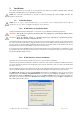
3. To proceed with the installation click “Next”. The following screen will be shown. 4. Please enter your user information and click “Next” to continue. If the program finds that there is still Acqiris software installed on your machine a warning panel (not shown) will appear. Otherwise, the next screen shows: 5. Pick the desired combination of module families and click "Next" to continue.
6. The screen above will normally allow the documentation to be installed. Remove the check from the box if you do not want online access to the manuals. 7. The next screen allows you to enable LabVIEW RT and/or Wind River VxWorks support. By default there will be none but if desired you can install any of them together with Windows support or without Windows support. Click “Next” to continue.
8. The screen below asks for the desired installation type. After having made your choice Click “Next” to continue. 9. If you chose the Custom installation, the following screen will let you select each package individually. Note that the space indicated for LabVIEW, Firmware and UserManual packages is incorrect. The correct values are 4.1 MB, 21 MB, and 27 MB respectively. 10. If MATLAB is installed on your machine, you will be asked to point the installer to the MATLAB root directory.
12. Furthermore, you should give a name to the shortcut folder. This is the menu entry under Start → Programs where you will find the shortcuts for AcqirisLive, manual(s), etc. 13. If you have enabled the installation of 12-bit Digitizers, Averagers, or Analyzers, the next screen lets you change the name of the directory where the FPGA firmware will be installed.
14. AcqirisLive needs the LabWindows/CVI 7.0 Run-Time Engine to run. If Setup has detected that a LabWindows/CVI Run-Time Engine is already installed on your system, it will ask you if you would like to install it locally for AcqirisLive anyway. If you are not sure about the version of the CVI Run-Time Engine on your system, it is recommended to install it locally. Click “Next” to continue. 15. Depending on the install type, you may be asked which LabVIEW version format you want for the LabVIEW files.
16. A summary will be shown to allow you to check what you have asked for 17. You are now ready to install. You may still go back to any previous screen to modify your selection. Click “Install” when ready.
. Setup will now copy the files and make the necessary changes to your system. When done, an information screen will be displayed. Please read this carefully. 19. Registration of your installation will help us provide you with better support. You will also be notified of updates and upgrades. All information submitted to us will be treated confidentially and never be disclosed outside the company.
20. Setup will prepare a registration e-mail in your e-mail client application upon termination of the setup procedure. You can then decide whether or not you wish to send it. You may also add comments. Uncheck the box if you do not want to register your installation.
21. Click “Finish”. The software installation is now complete. 22. You can now either accept the suggestion to restart the computer or you should shutdown your computer and proceed with the hardware installation. 2.3. Installing the Software for Linux The Acqiris Software is ready to install and run on Linux systems with any of the following: RedHat Enterprise Linux Version 3 - Kernel Version 2.4.21-4.EL RedHat Enterprise Linux Version 3 - Kernel Version 2.4.21-4.ELsmp, Suse Linux 9.
Debian Sarge 3.1 2.6.8-3-686, Debian 4.0 etch Kernel version 2.6.18-4-686, Scientific Linux 4.4 Kernel version 2.6.9-11.EL) The following tar files exist with the driver and library compiled with the GNU gcc version shown: AcqirisLinux-3.1a-gcc-3.3.tar.gz - compiled under Suse 9.2 with GNU gcc 3.3. AcqirisLinux-3.1a-gcc-3.4.tar.gz - compiled under SL 4.4 with GNU gcc 3.4. AcqirisLinux-3.1a-gcc-4.1.tar.gz - compiled under Debian etch with GNU gcc 4.1.
make clean to remove all *.o files in AcqirisLinux/linuxdriverpci. make to generate a new kernel mode driver acqrsPCI.o and also copy it to the directory AcqirisLinux/lib/modules where the install script (drv_install) can access it. drv_install rem to remove the previous installed kernel mode driver. drv_install add to install the new driver. To compile a new kernel under linux-2.6, issue the following commands: cd linux2.
2.4. 1. Installing the Hardware Turn off the power of the PC and the crate in the case of a CompactPCI module. For PCI modules the PC should be unplugged to ensure that the PCI bus has no power available. However, CompactPCI crates can be left plugged in since this ensures proper grounding. CAUTION: Touch the antistatic package to a grounded metal part of the PC or crate before removing the card from the package. Electrostatic discharge can damage the card. 2.
To proceed with the installation click "No, not this time" and then “Next”. The following window will appear: To proceed with the installation click “Next”.
and then NOTE: In some systems an application program (such as AcqirisLive) will not yet work correctly at this point. One additional boot cycle may be needed if this is the first time that a hardware board is being installed.
2.6. LabVIEW RT During program development you can choose whether you use LabVIEW or LabVIEW RT compatible libraries by switching the version present in National Instruments\LabVIEW m.n\instr.lib\. This swap can be facilitated by using the Install VI library for LabVIEW or LabVIEW Real-Time shortcut available in the Shortcut folder under Start → Programs. There is only one Acqiris Driver. It supports all Acqiris Instruments. The instructions below concern LabVIEW RT as used in NI PXI processors.
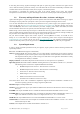
3. Product Description 3.1. Overview Simplified Block Diagram once for each channel Signal Input 10-bit 10- bit Input Signal Amplifier SH + ADC DEMUX 256K Acq Mem 50 Ohms TIMEBASE trigger Input Trigger Signal Amplifier TRIGGER circuit Thr DAC 50 Ohms Cal DAC Card Controller PCI Interface PCI Bus The 10-bit DC series products are CompactPCI/PXI compliant and require an appropriate CompactPCI crate.
3.2. Channel Input The 10-bit digitizer family can be configured with a variety of front-end mezzanine boards offering different capabilities. The currently available front end options are detailed below: Front End Option Standard Impedance Bandwidth Guaranteed (typical) / Risetime BW Limiter selections FS Voltage Ranges Maximum Offset / Max. Voltage 50 Ω 2 GHz 20, 200, 700 MHz 0.05 – 5.0 V ±5V 950 MHz ( 1 GHz) 0.35 ns 20, 200, 700 MHz 0.05 – 5.0 V HighImpedance (300 MHz) 1.
3.2.5. Bandwidth and Rise Time The bandwidth specification indicates the frequency at which an input signal will be attenuated by 3 dB (approximately 30% loss of amplitude). The bandwidth also affects the minimum rise and fall times that can be passed through the front-end electronics. A pulse with a very sharp edge will be observed to have a minimum rise time (τmin) determined by the front-end electronics.
3.3. Data Acquisition The table below summarizes the characteristics discussed in the sections that follow: Model Agilent # DC122 Max. Sampling Rate Max. CONVERTERS PER CHANNEL/ CHANNELS Default Memory points/ channel Maximum Optional Memory Maximum Segments points/ channel 4 GS/s 1/1 512K -- 1K 4 GS/s 2/2 256K -- 1K 8 GS/s 1/1 1024K 1G 125K 8 GS/s 2/2 512K 512M 125K 8 GS/s 4/4 256K 256M 125K U1062A DC152 U1062A DC222 U1065A DC252 U1065A DC282 U1065A 3.3.1.
The Single Acquisition mode is the normal operation of most digitizer products. In this mode an acquisition consists of a waveform recorded with a single trigger. The user selects the sampling rate and acquisition memory size and sets the number of segments to 1 (default value). The Sequence Acquisition mode allows the capture and storage of consecutive “single” waveforms.
This cannot be done in larger crates such as the Acqiris CC121. The actual transfer speed obtainable will depend on many other system characteristics. 3.4. Trigger Normally the trigger settings applied to the digitizer are used to determine the time at which the device will stop acquiring data. They are also capable of a ‘Start on Trigger’ mode of acquisition (see the Programmer’s Guide for further details). The various trigger settings are outlined below. 3.4.1.
3.4.8. Pre- and Post-Trigger Delay To increase trigger flexibility a pre- or post-trigger delay can be applied to the trigger position. The amount of pre-trigger delay can be adjusted between 0 and 100% of the acquisition time window (i.e. sampling interval x number of samples), whereas the post-trigger delay can be adjusted within the time interval corresponding to [0, 235 – 1 samples].
A full internal calibration of a digitizer can be very time consuming (> 100 s/digitizer), in particular for the HZ models. Therefore, several other options are available. They are documented in the Programmer's Reference Manual. A program can always be started with the digitizer in an uncalibrated state and data taken can be used for many kinds of testing.
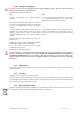
NOTE: The External Trigger Output functionality is implemented in the hardware. No Trigger Out signal occurs for software-generated triggers such as those of the AUTO mode of AcqirisLive or through the use of the function AcqrsD1_forceTrigger. However, AcqrsD1_forceTriggerEx does generate the signal. Trigger Output Block diagram: Signal: 1.6V swing 0v centered 50 Ohm Trigger Out G=1 0.8 V) The output swing is 1.6 V (± Offset: +/-2.5 V when unloaded and 0.8 V when and fall terminated on 50 Ω.
Crate DC1x2 all models DC2x2 Default Memory DC2x2 Optional Memory CC103 / CC105 None None None CC108 normal and low power None 4 4 CC108-600 None 7 4 CC121 None 15 9 If a third party crate is being used please check that the current drawn at 3.3 V does not sag below the effective PCI allowed tolerance at the beginning of the acquisition. The digitizers can use the PCI Bus at 32-bit − 33 MHz, all models, or at 64-bit − 66 MHz, DC2x2 only .
Complies with EN61326-1: Industrial Environment EMC Emissions Complies with EN61326-1: Class A for radiated emissions Required Airflow > 2 m/s in situ User Manual: Family of 10-bit Digitizers Page 37 of 55
4. Running the AcqirisLive Application AcqirisLive is an application to control and demonstrate the capabilities of Acqiris Digitizers on a single machine. AcqirisMAQS is a more advanced application offering many interesting possibilities for the control of acquisition systems in a single or multi-machine environment. Ask your salesman or Acqiris for more information. 4.1.
4.2. DSO TR Control Panel and Functions 4.2.1. Control Panel Mode In AcqirisLive there are two control panel modes available, Oscilloscope Mode and Transient Recorder Mode. The choice of mode is entirely determined by the preference of the user. Both modes provide the same set of functional capabilities but display the settings slightly differently.
Oscilloscope Mode Transient Recorder Mode 4.2.2. Displaying Multiple Traces If multi-channel modules, or several single channel modules, are installed on the PCI bus, multiple waveform displays, one from each installed channel, are overlaid on the display. The current channel is selected by clicking on the channel name within the upper portion of the control panel. The vertical settings of the current channel and the timebase and trigger of the correspondent digitizer are then indicated.
As an alternative to controlling the channels to be displayed from the control panel you can also control them by selecting the desired channels from the list of channel gains shown at the right hand side of the display window. Pressing the Finder button at the top of the control panel will identify the module associated with the current channel. When the finder button is depressed, the LED on the front panel lights up yellow on the digitizer module with the current channel. 4.2.3.
1. Clicking on the white numeric display of the voltage scale will show a pop-up list. Select the desired gain setting with the mouse pointer. 2. Clicking on the Decrement / Increment icons will step the voltage scale up or down to the next level for each click of the mouse. 3. Clicking Max / Min will toggle to the least sensitive gain setting or to the most sensitive gain setting. The input Coupling can be set for AC or DC.
discussion, a valid trigger indicates a trigger signal meeting the trigger conditions at a time when the digitizer is armed and ready to acquire data. In Single and Normal modes the display will only be updated after each active digitizer has received a trigger. Stop will stop the acquisition and hold the latest complete acquisition on the display. Single mode is used in order to capture one event at the first valid trigger.
• Make sure the maximum number of samples (MAX samples in Memory panel) is large enough. • Select the desired time per division setting (timebase panel): the fastest sampling rate for the current digitizer, compatible with the maximum number of samples, will be selected and applied to all digitizers in the system. Any digitizer not capable to satisfy that sampling rate will run at its closest setting.
image below. To clear the display in persistence display mode, press the “Clear” button that appears on the main display window. 4.3. Top Line Menu of AcqirisLive The top line menu contains functions offering additional utility to the AcqirisLive application.
Selecting the “Write files at end option” acquires all waveforms into memory first, before converting to the selected format and writing the data to disk. This option allows for faster data capture times. Selecting the “Show waveforms” allows the user to see the waveforms before writing them to disk. When all parameters are selected, click OK, and then select Normal, Auto or Single acquisition mode.
waveform display window. The time window displayed can be manipulated by allocating more or less memory to the acquisition. The External 10 MHz Reference in AcqirisLive is designed to work either in Oscilloscope mode or in Transient Recorder mode. The timebase and sample rate for waveform capture is fully selectable when using the external reference, just as it is when using the digitizer’s own internal reference clock. 4.9.
-l low priority process -m medium priority process -n no DMA for data transfers -p Use acquisition polling -r start in Transient Recorder (digitizer) mode -s simulation mode -t temperature update off -v show acquisition state -x disable automatic multi-instruments Operation Mode Acqiris averagers can be operated in Averager Mode or in standard Digitizer Mode.
When the program checks for an event from the operating system (e.g. to react to user input), it can put itself to sleep for a specified period of time. This gives other applications more processor time, but limits the performance of AcqirisLive in terms of maximum acquisition rate. The default is not to go to sleep, but this can be overridden to allow better performance for other applications. Note that this sleep policy is only in effect while the acquisition is running.
5. Running the GeoMapper Application 5.1. Who needs a Geographical Map of Modules The GeoMapper application gives the user the possibility of telling the Acqiris driver crucial details of the physical position of modules when this information cannot be deduced directly. It allows the driver to correctly adjust trigger 2 and clock delays between the different modules of an ASBus multi-Instrument and arrange the modules in an intuitive order.
Selecting a row will cause all of the LED's of modules in that Bus to be turned on RED. This should make it easy to identify which crate the modules are in. The third step is to specify the number of slots in each crate. This is shown below: The 4th step consists of arranging the modules of each crate into the correct order. The menu shown below is one in which all of this work has been done for the modules of a fully populated CC121. Selecting a position will cause a module to have its red LED turned on.
The GeoMapper application will always work with the standard AqGeo.map file. If you need to have several such files corresponding to different configurations it is up to you to either rename the files or transfer them to other directories in an appropriate manner.
6.
7.
8.