Agilent U3606A Multimeter|DC Power Supply User’s and Service Guide Agilent Technologies
Notices © Agilent Technologies, Inc., 2009–2014 Warranty No part of this manual may be reproduced in any form or by any means (including electronic storage and retrieval or translation into a foreign language) without prior agreement and written consent from Agilent Technologies, Inc. as governed by United States and international copyright laws. The material contained in this document is provided “as is,” and is subject to being changed, without notice, in future editions.
Safety Symbols The following symbols on the instrument and in the documentation indicate precautions which must be taken to maintain safe operation of the instrument.
General Safety Information IV WA R N I N G • Do not exceed any of the measurement limits defined in the specifications to avoid instrument damage and the risk of electric shock. • Do not use the device if it is damaged. Before you use the device, inspect the casing. Look for cracks or missing plastic. Do not operate the device around explosive gas, vapor, or dust. • Always use the device with the cables provided. • Observe all markings on the device before establishing any connection.
Environmental Conditions This instrument is designed for indoor use and in an area with low condensation. The table below shows the general environmental requirements for this instrument.
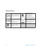
Regulatory Markings The CE mark is a registered trademark of the European Community. This CE mark shows that the product complies with all the relevant European Legal Directives. The C-tick mark is a registered trademark of the Spectrum Management Agency of Australia. This signifies compliance with the Australia EMC Framework regulations under the terms of the Radio Communication Act of 1992. ICES/NMB-001 indicates that this ISM device complies with the Canadian ICES-001.
Waste Electrical and Electronic Equipment (WEEE) Directive 2002/96/EC This instrument complies with the WEEE Directive (2002/96/EC) marking requirement. This affixed product label indicates that you must not discard this electrical or electronic product in domestic household waste. Product Category: With reference to the equipment types in the WEEE directive Annex 1, this instrument is classified as a “Monitoring and Control Instrument” product. The affixed product label is as shown below.
In This Guide… 1 Getting Started This chapter prepares the U3606A Multimeter|DC Power Supply for use, and contains a brief description of the instrument front panel, display, keypad, terminals, and rear panel. 2 Digital Multimeter Operation This chapter contains detailed information on how to take measurements using the U3606A Multimeter|DC Power Supply. It also describes the various multimeter functions and features available in the U3606A.
8 Characteristics and Specifications This chapter specifies the characteristics, environmental conditions, and specifications of the U3606A. 9 List of Error Messages The U3606A error messages are summarized in this chapter.
Declaration of Conformity (DoC) The Declaration of Conformity (DoC) for this instrument is available on the Web site. You can search the DoC by its product model or description. http://regulations.corporate.agilent.com/DoC/search.htm NOTE X If you are unable to search for the respective DoC, please contact your local Agilent representative.
Table of Contents Table of Contents 1 Getting Started Introduction 2 Measurement features Output features 3 System features 3 2 Initial Inspection 4 Standard purchase items 4 Connecting Power to the Instrument Adjusting the Handle 6 To Rack Mount the Instrument Stacking the Instrument 5 7 8 Product at a Glance 9 Product dimensions 9 The front panel at a glance 10 The display at a glance 11 The keypad at a glance 14 The terminals at a glance 19 The rear panel at a glance 22 2 Digital Multimeter
Table of Contents Performing diode tests Selecting a Range 51 54 Setting the Resolution 55 Math Operations 56 Null 57 dBm measurements 59 dB measurements 60 MinMax 62 Limit 64 Hold 67 Triggering the Multimeter 69 Front panel triggering 70 Remote interface triggering 3 71 DC Power Supply Operation Basic Operation 74 Constant voltage (CV) mode Constant current (CC) mode Protection Functions 78 Overvoltage protection (OVP) Overcurrent protection (OCP) Overvoltage limit (OV) 84 Overcurrent limit (OC) 8
Table of Contents Remote Sensing 4 99 System Related Operation Using the Utility Menu 108 Changing configurable settings 109 Utility Menu Summary 111 Reading error messages 114 Reading the program code revision 115 Adjusting the display brightness 116 Changing the power-on state 116 Configuring the beeper 117 Connecting to a remote interface 118 Performing a self-test 120 Selecting a dBm reference resistance value 121 Setting the output protection state 122 Configuring the ramp signal parameters 123 C
Table of Contents Using an electronic load 143 Connecting the current monitoring resistor Test Considerations 143 144 Input Connections 145 Zero offset verification test setup 145 Gain verification test setup 146 Output verification test setup 147 Verification and Performance Tests Overview Self-test 152 153 Performance Verification Tests 154 Zero offset verification test 154 Gain verification test 156 Output verification test 161 Additional Verification Tests 171 Optional capacitance gain verificati
Table of Contents Resetting the security code to the factory default Calibration Count 183 186 Calibration Message 187 Using the Front Panel for Adjustments 188 Selecting the adjustment mode 188 Entering adjustment values 188 Aborting a calibration in progress 189 General calibration procedure 190 Adjustments procedures 193 Zero offset adjustment 193 Gain adjustments 195 Output adjustments 208 Finishing the adjustments 217 7 Disassembly and Repair Operating Checklist 220 Cleaning 221 Fuse Replacem
Table of Contents Digital Multimeter Specifications 242 Specification assumptions 242 DC specifications 242 AC specifications 245 Frequency specifications 246 Duty cycle and pulse width specifications Operating specifications 248 Supplementary characteristics 249 247 DC Power Supply Specifications 253 Safety considerations 253 Specifications assumptions 253 Performance specifications 254 Supplementary characteristics 255 9 List of Error Messages Error Messages 260 Command errors 261 Execution errors 26
List of Figures List of Figures Figure 1-1 Figure 1-2 Figure 1-3 Figure 1-4 Figure 1-5 Figure 1-6 Figure 1-7 Figure 1-8 Figure 2-1 Figure 2-2 Figure 2-3 Figure 2-4 Figure 2-5 Figure 2-6 Figure 2-7 Figure 2-8 Figure 2-9 Figure 3-1 Figure 3-2 Figure 3-3 Figure 3-4 Figure 5-1 Figure 5-2 Figure 5-3 Figure 5-4 Figure 5-5 Figure 5-6 Figure 5-7 Figure 5-8 Figure 5-9 U3606A User’s and Service Guide U3606A handle adjustments 6 U3606A stacking directions 8 U3606A dimensions 9 U3606A front panel 10 VFD full display
List of Figures Figure 5-10 Figure 5-11 Figure 5-12 Figure 5-13 Figure 6-1 XVIII Test setup for CC line and load regulation verification 150 Test setup for CC noise effect verification 150 Test setup for square-wave output verification 151 Load transient response time 166 SECUR pads location 184 U3606A User’s and Service Guide
List of Tables List of Tables Table 1-1 Table 1-2 Table 1-3 Table 1-4 Table 2-1 Table 2-2 Table 2-3 Table 2-4 Table 2-5 Table 2-6 Table 2-7 Table 2-8 Table 2-9 Table 2-10 Table 2-11 Table 2-12 Table 3-1 Table 4-1 Table 4-2 Table 4-3 Table 4-4 Table 5-1 U3606A display annunciators 11 U3606A keypad functions 15 Input terminal connections for measurement functions 20 Output terminal connections for source functions 21 DC voltage measurement summary 26 AC voltage measurement summary 27 DC current measurement
List of Tables Table 5-13 Table 5-14 Table 5-15 Table 5-16 Table 5-17 Table 5-18 Table 6-1 Table 6-2 Table 6-3 Table 6-4 Table 6-5 Table 6-6 Table 6-7 Table 6-8 Table 6-9 Table 6-10 Table 6-11 Table 6-12 Table 7-1 Table 8-1 Table 8-2 Table 8-3 Table 8-4 Table 8-5 Table 8-6 Table 8-7 Table 8-8 Table 8-9 Table 8-10 Table 8-11 Table 9-1 Table 9-2 Table 9-3 Table 9-4 Table 9-5 Table 9-6 Table 9-7 XX test 167 Constant current load effect verification test 168 Constant current source effect verification test 1
U3606A Multimeter|DC Power Supply User’s and Service Guide 1 Getting Started Introduction 2 Measurement features 2 Output features 3 System features 3 Initial Inspection 4 Standard purchase items 4 Connecting Power to the Instrument 5 Adjusting the Handle 6 To Rack Mount the Instrument 7 Product at a Glance 9 Product dimensions 9 The front panel at a glance 10 The display at a glance 11 The keypad at a glance 14 The terminals at a glance 19 The rear panel at a glance 22 This chapter prepares the U3606A Mu
1 Getting Started Introduction Introduction The Agilent U3606A Multimeter|DC Power Supply unit is a combination of a 5½ digit digital multimeter and a 30 W single output dual- range DC power supply with a square- wave generator. These two distinctive modules are able to work simultaneously (excand independently, providing an efficient, convenient, and affordable testing solution. The U3606A has the dimensions of 2½U (rack unit) high, and provides the flexibility for bench or rack- mounted use.
Getting Started Introduction 1 Output features • Single- output dual range — S1 (30 V/1 A) or S2 (8 V/3 A) • Constant voltage and constant current supply • Overvoltage and overcurrent protection • Remote sensing to compensate for voltage drop in load leads • Square- wave generator with selectable amplitude, frequency, duty cycle, and pulse width parameters • Output on standby when disabled • Ramp signal capability with fixed time for preset step and end amplitude • Scan signal capability with preset time,
1 Getting Started Initial Inspection Initial Inspection When you receive your instrument, inspect the unit for any obvious damage such as broken terminals or cracks, dents, and scratches on the casing that may occur during shipment. If any damage is found, notify the nearest Agilent Sales Office immediately. The front of this manual contains the warranty information. Standard purchase items Verify that you have received the following items with your unit.
Getting Started Connecting Power to the Instrument 1 Connecting Power to the Instrument Connect the power cord to the AC power connector (see “The rear panel at a glance” on page 22 for the AC power connector location). The mains plug should only be inserted into a socket outlet that provides protective earth contact. Push the power switch to turn on the instrument. The front- panel display illuminates while the U3606A performs its power- on self- test.
1 Getting Started Adjusting the Handle Adjusting the Handle To adjust the handle, grasp the handle by the sides and pull outward. Then, rotate the handle to the desired position. The various positions available are illustrated below.
Getting Started To Rack Mount the Instrument 1 To Rack Mount the Instrument You can mount the U3606A in a standard 19- inch rack cabinet using one of the three optional kits available. Instructions and mounting hardware are included with each rack- mounting kit. Any Agilent Technologies instrument of the same size can be rack- mounted beside the U3606A Multimeter|DC Power Supply. 1 Remove the carrying handle and the front and rear rubber bumpers before rack- mounting the instrument.
1 Getting Started Stacking the Instrument Stacking the Instrument If you have purchased more than one unit of the U3606A Multimeter|DC Power Supply, you can stack the units on top of each other. The warning sign Stackable Direction located at the bottom side of the front and back rubber bumpers indicate the orientation of the rubber bumpers. The rubber bumpers are uniquely designed to firmly secure the units stacked above it, preventing any unwanted movements.
Getting Started Product at a Glance 1 Product at a Glance Product dimensions 105 mm 329 mm 255 mm Figure 1-3 U3606A dimensions U3606A User’s and Service Guide 9
1 Getting Started Product at a Glance The front panel at a glance 1 2 3 5 7 8 4 6 Figure 1-4 U3606A front panel Item 10 Description 1 Source terminals Positive (FORCE +) and negative (FORCE –) connector terminals for source operation and 4-wire low-resistance measurement. 2 VFD display Displays the instrument settings and readings. See “The display at a glance” on page 11 for a complete list of all display annunciators.
Getting Started Product at a Glance 1 The display at a glance Figure 1-5 VFD full display with all segments illuminated To view the full display (with all segments illuminated), press and hold Hold while powering- on the U3606A. After you are done viewing the full display, press Hold again to resume normal operation.
1 Getting Started Product at a Glance Table 1-1 U3606A display annunciators (continued) Annunciator Description AC measurement selected AC+DC measurement selected ºC Celsius temperature unit (feature not applicable with the U3606A) ºF Fahrenheit temperature unit (feature not applicable with the U3606A) dB Decibel unit relative to 1 dBm dBm Decibel unit relative to 1 mW ms Pulse width unit % Duty cycle unit MkΩ Resistance units: Ω, kΩ, MΩ MkHz Frequency units: Hz, kHz, MHz mV Voltage unit
Getting Started Product at a Glance 1 Table 1-1 U3606A display annunciators (continued) Annunciator Description Store Store instrument state selected Recall Recall instrument state selected Ramp Ramp signal output selected Scan Scan signal output selected Error One or more errors available in the error queue Rmt Remote interface control is active OV Overvoltage condition active OC Overcurrent condition active OUT Output is enabled from the output (+ FORCE –) terminals and remote sense (
1 Getting Started Product at a Glance The keypad at a glance Figure 1-6 U3606A keypad with both multimeter and source operations The operation of each key is shown below. Pressing a key changes the current operation, illuminates a related annunciator on the display, and generates a key- click sound (a beep). Using the Shift key The front panel has two rows of keys to select various functions and operations. Most keys have a shifted function printed in blue above the key.
Getting Started Product at a Glance 1 Table 1-2 U3606A keypad functions Key Description System related operation Push Power to turn on or turn off the U3606A Multimeter|DC Power Supply. • Press Shift to perform a shifted function. See “Using the Shift key” on page 14 for more information. • Press Shift to unlock the front-panel keys when in remote operation lock. See “Remote Operation” on page 134 for more information. Press Shift > Utility to access the utility menu.
1 Getting Started Product at a Glance Table 1-2 U3606A keypad functions (continued) Key Description Press Shift > Recall to recall a previously stored instrument state. See “Recalling a stored state” on page 133 for more information. Multimeter operation Press V to cycle between the DC, AC, and AC+DC voltage measurement functions. See “Performing voltage measurements” on page 25 for more information. Press I to cycle between the DC, AC, and AC+DC current measurement functions.
Getting Started Product at a Glance 1 Table 1-2 U3606A keypad functions (continued) Key Description Press MinMax to store statistical data for the current readings. See “MinMax” on page 62 for more information. Press Shift > Limit to enable the limit math operation. See “Limit” on page 64 for more information. Press Hold to capture and hold a reading within the specified variation and threshold values.[2] See “Hold” on page 67 for more information.
1 Getting Started Product at a Glance Table 1-2 U3606A keypad functions (continued) Key Description • Press to select the square-wave output. Use the directional keys to set the voltage amplitude. • Press again to cycle through the duty cycle, pulse width, and voltage amplitude settings. • See “Square-wave Output” on page 88 for more information. When the frequencies.
Getting Started Product at a Glance 1 [3] The continuity and diode test functions have a fixed 4½ digit resolution. Capacitance measurement is fixed to 3½ digit resolution. [4] The sweep functions can only be accessed when the U3606A is in constant voltage or constant current mode. You cannot access the sweep functions while the U3606A is in square-wave output mode. [5] The overcurrent and overvoltage protection features are only active when the output protection state is enabled.
1 Getting Started Product at a Glance Table 1-3 Input terminal connections for measurement functions Function Input terminals (+ SENSE –) 1000 Vrms on all ranges, < 0.3 A short circuit DC voltage measurement AC voltage measurement Input protection V LO 750 Vrms on all ranges Frequency, duty cycle, and pulse width measurement via the voltage path Capacitance measurement LO 1000 Vrms on all ranges, < 0.3 A short circuit Diode test LO 1000 Vrms on all ranges, < 0.
Getting Started Product at a Glance 1 Table 1-4 Output terminal connections for source functions Function Output terminals (+ FORCE –) Maximum output Constant voltage output • Amplitude: 0 V to 30 V[1] • OCP • S1: 0 A to 1.1 A • S2: 0 A to 3.3 A • OC: • S1: 0 A to 1.05 A • S2: 0 A to 3.15 A Constant current output • Amplitude: 0 A to 3 A[1] • OVP: • S1: 0 V to 33 V • S2: 0 V to 8.8 V • OV: • S1: 0 V to 31.5 V • S2: 0 V to 8.
1 Getting Started Product at a Glance The rear panel at a glance 3 1 4 5 2 9 7 6 8 Figure 1-8 U3606A rear panel Item 22 Description 1 AC power connector Plug the power cord firmly into the power receptacle on the rear panel of the instrument. See “Connecting Power to the Instrument” on page 5 for more information. 2 AC line fuse To maintain protection, replace this fuse only with a fuse of the specified type and rating.
U3606A Multimeter|DC Power Supply User’s and Service Guide 2 Digital Multimeter Operation Making Measurements 24 Performing voltage measurements 25 Performing current measurements 29 Performing resistance (2-wire) measurements 33 Performing low-resistance (4-wire) measurements 35 Performing frequency, pulse width, and duty cycle measurements 38 Performing capacitance measurements 46 Performing continuity tests 49 Performing diode tests 51 Selecting a Range 54 Setting the Resolution 55 Math Operations 56 Nu
2 Digital Multimeter Operation Making Measurements Making Measurements The following pages introduce the many types of measurements that you can make with the U3606A, and how to make the connections for each measurement. NOTE • Most basic measurements can be made using the instrument factory default settings. • For remote operation, refer to the MEASure, CONFigure, and CALCulate subsystem in the U3606A Programmer’s Reference.
Digital Multimeter Operation Making Measurements 2 Performing voltage measurements Making the connections Connect the test leads as shown below: – AC or DC voltage source + Figure 2-1 Terminal connections for voltage measurements NOTE • The U3606A will automatically select a suitable range for voltage measurements by default (autoranging). To manually select a range, see “Selecting a Range” on page 54 for more information. • The U3606A resolution is set to 5½ digits by default.
2 Digital Multimeter Operation Making Measurements Measuring DC voltage 1 Press V to make DC voltage measurements. (The DC annunciator is shown on the display.) DC annunciator Table 2-1 DC voltage measurement summary Item Description Available ranges 19.9999 mV, 100.000 mV, 1.00000 V, 10.0000 V, 100.000 V, 1000.00 V Measurement method Sigma Delta A-to-D converter Input impedance 10 MΩ ± 2% range (typical) in parallel with capacitance < 120 pF Input protection 1000 Vrms on all ranges, < 0.
Digital Multimeter Operation Making Measurements 2 Measuring AC voltage 1 Press V again (until the AC annunciator is shown on the display) to make AC voltage measurements. AC annunciator Table 2-2 AC voltage measurement summary Item Description Available ranges 100.000 mV, 1.00000 V, 10.0000 V, 100.000 V, 750.
2 Digital Multimeter Operation Making Measurements Measuring AC+DC voltage The U3606A Multimeter|DC Power Supply includes a true- rms multimeter that returns an accurate rms reading not only for sine waves, but also other AC signals such as square, triangle, and staircase waveforms without any DC offset. However, you may choose to return the measured AC signal with DC offset by using the AC+DC function. The AC+DC voltage measurement measures AC voltage with DC offset.
Digital Multimeter Operation Making Measurements 2 Performing current measurements Making the connections Connect the test leads as shown below: – AC or DC current source + Figure 2-2 Terminal connections for current measurements NOTE • The U3606A will automatically select a suitable range for current measurements by default (autoranging). To manually select a range, see “Selecting a Range” on page 54 for more information. • The U3606A resolution is set to 5½ digits by default.
2 Digital Multimeter Operation Making Measurements Measuring DC current 1 Press I to make DC current measurement. (The DC annunciator is shown on the display.) DC annunciator Table 2-3 DC current measurement summary Item Description Available ranges 10.0000 mA, 100.000 mA, 1.00000 A, 3.0000 A Measurement method Sigma Delta A-to-D converter Burden voltage and shunt resistance • • • • Input protection Protected with a 3.15 A/500 V, FF fuse < 0.2 V, 10 Ω for 10 mA range < 0.
Digital Multimeter Operation Making Measurements 2 Measuring AC (rms) current 1 Press I again (until the AC annunciator is shown on the display) to make AC current measurements. AC annunciator Table 2-4 AC current measurement summary Item Description Available ranges 10.0000 mA, 100.000 mA, 1.00000 A, 3.0000 A Measurement method AC coupled true rms Burden voltage and shunt resistance • • • • Input protection Protected with a 3.15 A/500 V, FF fuse Crest factor For < 5:1 errors included.
2 Digital Multimeter Operation Making Measurements Measuring AC+DC current The U3606A Multimeter|DC Power Supply includes a true- rms multimeter that returns an accurate rms reading not only for sine waves, but also other AC signals such as square, triangle, and staircase waveforms without any DC offset. However, you may choose to return the measured AC signal with DC offset by using the AC+DC function. The AC+DC current measurement measures AC current with DC offset.
Digital Multimeter Operation Making Measurements 2 Performing resistance (2-wire) measurements CAUTION Disconnect circuit power and discharge all high-voltage capacitors before measuring resistance or conductance, or testing circuit continuity, to avoid damaging the U3606A or the device under test.
2 Digital Multimeter Operation Making Measurements Measuring resistance 1 Press to make 2- wire resistance measurements. Table 2-5 Resistance measurement summary Item Description Available ranges 100.000 Ω, 1.00000 kΩ, 10.0000 kΩ, 100.000 kΩ, 1.00000 MΩ, 10.0000 MΩ, 100.000 MΩ Measurement method Two-wire, open-circuit voltage limited to < 5 V Input protection 1000 Vrms on all ranges, < 0.
Digital Multimeter Operation Making Measurements 2 Performing low-resistance (4-wire) measurements CAUTION NOTE Disconnect circuit power and discharge all high-voltage capacitors before measuring resistance or conductance, or testing circuit continuity, to avoid damaging the U3606A or the device under test. DC power supply functions are locked The DC power supply functions are locked when you select the low-resistance (Lo Ω) measurements.
2 Digital Multimeter Operation Making Measurements Making the connections Connect the test leads as shown below: Resistance Test current Figure 2-4 Terminal connections for 4-wire resistance measurements NOTE • The U3606A will automatically select a suitable range for 4-wire low-resistance measurements by default (autoranging). To manually select a range, see “Selecting a Range” on page 54 for more information. • The U3606A resolution is set to 5½ digits by default.
Digital Multimeter Operation Making Measurements 2 Measuring low-resistance 1 Press Shift > Lo Ω to make 4- wire low- resistance measurements. (The Lo Ω annunciator is shown on the display.) Lo Ω annunciator Table 2-6 Low-resistance measurement summary Item Description Available ranges 100 mΩ, 1000 mΩ, 10 Ω Measurement method Four-wire, the test current is sent from the FORCE terminals and the resistance is measured by the SENSE terminals.
2 Digital Multimeter Operation Making Measurements Performing frequency, pulse width, and duty cycle measurements There are two measuring paths for the frequency, pulse width, and duty cycle measurements — voltage or current. Therefore, before setting the frequency measurement, it is advisable to configure the AC voltage (see “Measuring AC voltage” on page 27) or AC current (see “Measuring AC (rms) current” on page 31) measurements first.
Digital Multimeter Operation Making Measurements 2 Frequency source Figure 2-6 Terminal connections for frequency, pulse width, and duty cycle measurement via the current path NOTE • The range and resolution of the frequency, pulse width, and duty cycle measurement follows the configuration of the AC voltage or AC current measurement (dependant on the path chosen). • The U3606A will automatically select a suitable range for AC voltage and AC current measurements by default (autoranging).
2 Digital Multimeter Operation Making Measurements Measuring frequency — voltage path The range and resolution of the frequency measurement via the voltage path follows the configuration of the AC voltage measurement. 1 Press Hz ms % to make frequency measurements via the voltage path. The AC voltage measurement display will flash briefly before the frequency measurement display is shown. Table 2-7 Frequency measurement (voltage path) summary Item Description Available ranges 100.000 mV, 1.
Digital Multimeter Operation Making Measurements 2 Measuring pulse width — voltage path The range and resolution of the pulse width measurement via the voltage path follows the configuration of the AC voltage measurement. 1 Press Hz ms % to make frequency measurements via the voltage path. The AC voltage measurement display will flash briefly before the frequency measurement display is shown.
2 Digital Multimeter Operation Making Measurements Measuring duty cycle — voltage path The range and resolution of the duty cycle measurement via the voltage path follows the configuration of the AC voltage measurement. 1 Press Hz ms % to make frequency measurements via the voltage path. The AC voltage measurement display will flash briefly before the frequency measurement display is shown. 2 Press Hz ms % again (until the duty cycle annunciator is shown on the display) to make duty cycle measurements.
Digital Multimeter Operation Making Measurements 2 Measuring frequency — current path The range and resolution of the frequency measurement via the current path follows the configuration of the AC current measurement. 1 Press I > Hz ms % to make frequency measurements via the current path. The AC current measurement display will flash briefly before the frequency measurement display is shown. Table 2-8 Frequency measurement (current path) summary Item Description Available ranges 10.0000 mA, 100.
2 Digital Multimeter Operation Making Measurements Measuring pulse width — current path The range and resolution of the pulse width measurement via the current path follows the configuration of the AC current measurement. 1 Press I > Hz ms % to make frequency measurements via the current path. The AC current measurement display will flash briefly before the frequency measurement display is shown.
Digital Multimeter Operation Making Measurements 2 Measuring duty cycle — current path The range and resolution of the duty cycle measurement via the current path follows the configuration of the AC current measurement. 1 Press I > Hz ms % to make frequency measurements via the current path. The AC current measurement display will flash briefly before the frequency measurement display is shown.
2 Digital Multimeter Operation Making Measurements Performing capacitance measurements The U3606A Multimeter|DC Power Supply calculates capacitance by charging a capacitor with a known current for a period of time, and then measuring the voltage. Measuring tips: • For measuring capacitance values greater than 10000 μF, discharge the capacitor first, then select a suitable range for measurement. This will speed up the measurement time and also ensure that the correct capacitance value is obtained.
Digital Multimeter Operation Making Measurements 2 Making the connections Connect the test leads as shown below: – Capacitance + Figure 2-7 Terminal connections for capacitance measurements NOTE • The U3606A will automatically select a suitable range for capacitance measurements by default (autoranging). To manually select a range, see “Selecting a Range” on page 54 for more information. • The resolution for capacitance measurement is fixed to 3½ digits.
2 Digital Multimeter Operation Making Measurements Measuring capacitance 1 Press to make capacitance measurements. Table 2-9 Capacitance measurement summary Item Description Available ranges 1 nF, 10 nF, 100 nF, 1 μF, 10 μF, 100 μF, 1000 μF, 10000 μF Measurement method Computed from constant current source charge time, typical 0.2 V to 1.4 Vac signal level Input protection 1000 Vrms on all ranges, < 0.
Digital Multimeter Operation Making Measurements 2 Performing continuity tests CAUTION Disconnect circuit power and discharge all high-voltage capacitors before measuring resistance or conductance, or testing circuit continuity, to avoid damaging the U3606A or the device under test.
2 Digital Multimeter Operation Making Measurements Testing continuity 1 Press again (until the continuity annunciator is shown on the display) to make continuity measurements. Continuity annunciator Table 2-10 Continuity function summary Item Description Measurement method 0.83 mA ± 0.2% constant current source, open-circuit voltage limited to < 5 V Audible tone: Continuous beep when reading is less than threshold resistance of 10 Ω at 1.0 kΩ range Input protection 1000 Vrms on all ranges, < 0.
Digital Multimeter Operation Making Measurements 2 Performing diode tests CAUTION Disconnect circuit power and discharge all high-voltage capacitors before checking diodes to avoid damaging the U3606A or the device under test.
2 Digital Multimeter Operation Making Measurements NOTE The resolution for diode tests is fixed to 3½ digits. Checking diodes 1 Press again (until the diode annunciator is shown on the display) to make diode measurements. Diode annunciator Table 2-11 Diode function summary Item Description Measurement method 0.83 mA ± 0.2% constant current source Audible tone: • Continuous beep when level is below +50 mV DC • Single tone for normal forward-biased diode or semiconductor junction where 0.
Digital Multimeter Operation Making Measurements NOTE 2 The U3606A can display diode forward bias of up to approximately 1.2 V. The forward bias of a typical diode is within the range of 0.3 V to 0.8 V. 5 Reverse the probes and measure the voltage across the diode again (refer to Figure 2- 9 on page 51). Assess the diode according to the following guidelines: • A diode is considered good if the multimeter displays “OPEn” in reverse bias mode.
2 Digital Multimeter Operation Selecting a Range Selecting a Range You can allow the U3606A to automatically select the range using autoranging, or you can select a fixed range using manual ranging. Autoranging is convenient because the U3606A automatically selects the appropriate range for sensing and displaying each measurement. However, manual ranging results in better performance, since the U3606A does not have to determine which range to use for each measurement.
Digital Multimeter Operation Setting the Resolution 2 Setting the Resolution You can select either 4½ digit or 5½ digit resolution for the AC voltage, DC voltage, AC+DC voltage, AC current, DC current, AC+DC current, 2- wire resistance, and 4- wire low- resistance measurements. • 5½ digit readings have the best accuracy and noise rejection. • 4½ digit readings provide for faster readings.
2 Digital Multimeter Operation Math Operations Math Operations The U3606A Multimeter|DC Power Supply provides six math operations: null measurements, dB measurements, dBm measurements, statistics (MinMax) for accumulated readings, limit testing, and a hold function. The table below describes the math operations that can be used with each measurement function.
Digital Multimeter Operation Math Operations 2 Null When making null measurements, also called relative, each reading is the difference between a stored (selected or measured) null value and the input signal. One possible application is to increase the accuracy of a 2- wire resistance measurement by nulling the test lead resistance. Nulling the leads is also particularly important prior to making capacitance measurements.
2 Digital Multimeter Operation Math Operations Editing the null value 1 Press Null again to view and edit the null value. 2 Press or to select which digit position or range to be changed. 3 Press or to increase or decrease the value. 4 Press Shift > Save to save the changes. “donE” will be briefly displayed in the upper secondary display. The display will then return to normal. 5 Press Shift > Exit to exit the edit mode without saving.
Digital Multimeter Operation Math Operations 2 dBm measurements The logarithmic dBm (decibels relative to 1 mW) scale is often used in RF signal measurements. The U3606A takes a measurement and calculates the power delivered to a reference resistance (typically 50 Ω, 75 Ω, or 600 Ω). Voltage measurement is then converted to dBm. NOTE This math operation applies to voltage measurements only.
2 Digital Multimeter Operation Math Operations dB measurements Each dB measurement is the difference between the input signal and a stored relative value, with both values converted to dBm. When enabled, the dB operation computes the dBm value for the next reading, stores the dBm result into the relative value register and immediately produces the dB calculation.
Digital Multimeter Operation Math Operations 2 Editing the relative value 1 Press dB again to view and edit the relative value. 2 Press or to select which digit position or range to be changed. 3 Press or to increase or decrease the value. 4 Press Shift > Save to save the changes. “donE” will be briefly displayed in the upper secondary display. The display will then return to normal. 5 Press Shift > Exit to exit the edit mode without saving.
2 Digital Multimeter Operation Math Operations MinMax The MinMax operation stores the minimum and maximum values, the average, and the number of readings during a series of measurements. From the front panel, you can view the following statistical data for any set of readings: average or mean (Avg), maximum (Max), and minimum (Min). NOTE • This math operation applies to all measurement functions except continuity and diode test.
Digital Multimeter Operation Math Operations 2 Each time a new minimum, maximum, or average value is stored, the instrument beeps once (if the beeper is enabled). The U3606A calculates the average of all readings and records the number of readings taken since the MinMax function was enabled.
2 Digital Multimeter Operation Math Operations Limit The limit test function enables you to perform pass or fail testing to upper and lower limits that you specify. You can set the upper and lower limits to any value between 0 and ±120% of the highest range for the present measurement function. The upper limit value you select must be larger than the lower limit value. The initial factory settings for both values is zero.
Digital Multimeter Operation Math Operations 2 The primary display briefly shows “PASS” when readings are within the specified limits, “HI” when the reading is above the high limit, and “LO” when the reading is below the low limit. Each time the input value transitions from “PASS” to “HI” or from “PASS” to “LO”, or when transitioning directly from “HI” to “LO” or “LO” to “HI”, the instrument beeps once (if the beeper is enabled). Press Shift > Exit to exit the limit mode.
2 Digital Multimeter Operation Math Operations Editing the upper and lower limit values 1 Press Shift > Limit again to view and edit the upper (HI) and lower (LO) limit values. 2 Press or to toggle between the upper (HI) limit value and the lower (LO) limit value 3 Press or to begin editing the upper or lower limit value selected. 4 Press or to select which digit position or range to be changed.
Digital Multimeter Operation Math Operations 2 Hold The refresh hold feature allows you to capture and hold a reading, within the specified variation and threshold values, on the front panel display. This is useful in situations when you want to take a reading, remove the test probes, and have the reading remain on the display. When a stable reading is detected, the instrument beeps once (if the beeper is enabled), and holds the reading on the primary display.
2 Digital Multimeter Operation Math Operations Enabling the hold operation Press Hold to enable the hold operation. The Hold annunciator is illuminated and the hold function is enabled. Hold annunciator Press Hold again or Shift > Exit to exit the hold mode.
Digital Multimeter Operation Triggering the Multimeter 2 Triggering the Multimeter The U3606A Multimeter|DC Power Supply triggering system allows you to generate triggers either automatically or manually via the Trig key on the front panel or the *TRG command via the remote interface. From the front panel (local interface), the multimeter always auto- triggers by default. Auto triggering takes continuous readings at the fastest rate possible for the selected measurement configuration.
2 Digital Multimeter Operation Triggering the Multimeter Front panel triggering Single triggering The U3606A takes one reading each time you press Trig. NOTE The single trigger mode is available from the local interface only. Press Shift > Trig once to enable the single trigger mode. The Trig annunciator is illuminated and the single trigger function is enabled. Trig annunciator A single reading is taken, and another reading is taken each time you press Trig. (You do not need to press Shift again.
Digital Multimeter Operation Triggering the Multimeter 2 Remote interface triggering Immediate triggering In the immediate trigger mode, the trigger signal is always present. When you place the multimeter in the wait- for- trigger state, the trigger is issued immediately. This is the default trigger source for the U3606A Multimeter|DC Power Supply. NOTE The immediate trigger mode is available from the remote interface only.
2 Digital Multimeter Operation Triggering the Multimeter Remote interface operation: • The TRIGger:SOURce BUS command selects the bus trigger source. • The MEASure? command overwrites the bus trigger and triggers the U3606A and returns a measurement. • The READ? command does not overwrite the bus trigger, and if selected, generates an error. It will only trigger the instrument and return a measurement when the IMMEdiate trigger is selected.
U3606A Multimeter|DC Power Supply User’s and Service Guide 3 DC Power Supply Operation Basic Operation 74 Constant voltage (CV) mode Constant current (CC) mode Protection Functions 78 Overvoltage protection (OVP) Overcurrent protection (OCP) Overvoltage limit (OV) 84 Overcurrent limit (OC) 86 Square-wave Output 88 Sweep Functions 93 Ramp signal 93 Scan signal 95 Selecting a Range 97 Enabling the Output 98 Remote Sensing 99 74 76 78 81 This chapter contains examples on how to operate the DC power supply f
3 DC Power Supply Operation Basic Operation Basic Operation The U3606A has two basic operating modes: constant voltage and constant current mode. In constant voltage mode, the U3606A regulates the output voltage at the selected value, while the load current varies as required by the load. In constant current mode, the U3606A regulates the output current at the selected value, while the voltage varies as required by the load.
DC Power Supply Operation Basic Operation 3 Supplying constant voltage 1 Press Voltage to select the constant voltage mode. When the U3606A is operating in constant voltage mode, the CV annunciator on the front panel is illuminated. CV annunciator 2 The output voltage can be programmed when the output is enabled (OUT) or disabled (SBY). Ensure that the CV annunciator is flashing. (Press Voltage again if it is not.) 3 Press or to select which digit position to be changed.
3 DC Power Supply Operation Basic Operation Constant current (CC) mode Making the connections Connect the load as shown below: LOAD Figure 3-2 Constant current mode terminal connections 76 U3606A User’s and Service Guide
DC Power Supply Operation Basic Operation 3 Supplying constant current 1 Press Current to select the constant current mode. When the U3606A is operating in constant current mode, the CC annunciator on the front panel is illuminated. CC annunciator 2 The output current can be programmed when the output is enabled (OUT) or disabled (SBY). Ensure that the CC annunciator is flashing. (Press Current again if it is not.) 3 Press or to select which digit position to be changed.
3 DC Power Supply Operation Protection Functions Protection Functions Overvoltage protection (OVP) In constant current mode, the U3606A regulates the output current at the selected value, while the voltage varies as required by the load. The overvoltage protection protects against overvoltage conditions on the output.
DC Power Supply Operation Protection Functions 3 4 Press Shift > Save or Voltage (Protect) to save the changes. “donE” will be briefly displayed in the upper secondary display. The display will then return to normal. 5 Alternatively, press Shift > Exit or Shift > Protect to exit the edit mode without saving. NOTE • The OVP feature is always enabled by default whenever you select constant current mode. You can disable the OVP feature by disabling the output protection state from the utility menu.
3 DC Power Supply Operation Protection Functions Error number 510, “Voltage output over protection” will be recorded in the error queue when the OVP circuit trips. To read and clear the error message, see “Reading error messages” on page 114. For a complete list of all error messages, see Chapter 9, “List of Error Messages,” starting on page 259. NOTE Resetting the OVP condition Use one of the following methods to reset the OVP circuit after it activates.
DC Power Supply Operation Protection Functions 3 Overcurrent protection (OCP) In constant voltage mode, the U3606A regulates the output voltage at the selected value, while the load current varies as required by the load. The overcurrent protection will disable the output if the load effect exceeds the programmed protection value. This protection is useful when the load is sensitive to an overcurrent condition.
3 DC Power Supply Operation Protection Functions NOTE • The OCP feature is always enabled by default whenever you select constant voltage mode. You can disable the OCP by disabling the output protection state from the utility menu. See Chapter 4, “Setting the output protection state,” starting on page 122 for more information. • If the OCP value is set to a lesser value than the OC value, the OC value will be adjusted to equal the OCP value. • The OCP value is not applicable for square-wave output.
DC Power Supply Operation Protection Functions 3 Resetting the OCP condition Use one of the following methods to reset the OCP circuit after it activates. If the condition that caused the overcurrent shutdown is still present, the OCP circuit will turn the output off again. 1 When the OCP circuit trips, the U3606A will immediately prompt you to change the OCP trip level. Use the directional keys to select a higher OCP trip level and press Shift > Save or Voltage (Protect) to save the changes.
3 DC Power Supply Operation Protection Functions Overvoltage limit (OV) The overvoltage limit prevents the output voltage present across the load to change beyond the programmed overvoltage limit. If the load effect exceeds the programmed overvoltage limit, the CC output will be lowered to maintain the output power across the load. The combination of the OV and OVP features create a closed loop circuit protection for sensitive load behaviors.
DC Power Supply Operation Protection Functions NOTE 3 • The OV limit feature is always enabled by default whenever you select constant current mode. You cannot disable the OV limit feature. • If the OV value is set to a greater value than the OVP value, the OVP value will be adjusted to equal the OV value. • If the OV value is set to zero, this will result in the output current being dropped to zero for limiting. • The OV value is not applicable for square-wave output.
3 DC Power Supply Operation Protection Functions Overcurrent limit (OC) The overcurrent limit prevents the output current flowing through the load to change beyond the programmed overcurrent limit. If the load effect exceeds the programmed overcurrent limit, the CV output will be lowered to maintain the output power across the load. The combination of the OC and OCP features create a closed loop circuit protection for sensitive load behaviors.
DC Power Supply Operation Protection Functions NOTE 3 • The OC limit feature is always enabled by default whenever you select constant voltage mode. You cannot disable the OC limit feature. • If the OC value is set to a greater value than the OCP value, the OCP value will be adjusted to equal the OC value. • If the OC value is set to zero, this will result in the output voltage being dropped to zero for limiting. • The OC value is not applicable for square-wave output.
3 DC Power Supply Operation Square-wave Output Square-wave Output Square- wave output is a unique function for many applications, such as pulse width modulation (PWM) output, adjustable voltage control, and synchronous clock (baud rate generator). You can also use this function to check and calibrate flow- meter displays, counters, tachometers, oscilloscopes, frequency converter, frequency transmitter, and other frequency input devices.
DC Power Supply Operation Square-wave Output 3 Setting the amplitude 1 To set the square- wave amplitude, press until the amplitude value is displayed in the lower secondary display. Ensure that the square- wave annunciator ( ) on the front panel is flashing. (Press again if it is not.) Square-wave amplitude 2 Press or to select which digit position to be changed. 3 Press or to increase or decrease the value. 4 Press NOTE again or Shift > Save to save the changes.
3 DC Power Supply Operation Square-wave Output Setting the frequency 1 To set the square- wave frequency, press until the duty cycle or pulse width value is displayed in the lower secondary display. Ensure that the square- wave annunciator ( ) on the front panel is flashing. (Press again if it is not.) Square-wave frequency Ensure that either the duty cycle or pulse width value is displayed here 2 Press or to step through the available frequencies. (There are 27 frequencies choose from.
DC Power Supply Operation Square-wave Output 3 Setting the duty cycle 1 To set the square- wave duty cycle, press until the duty cycle value is displayed in the lower secondary display. Ensure that the square- wave annunciator ( ) on the front panel is flashing. (Press again if it is not.) Square-wave duty cycle 2 Press or to step through the available duty cycle values. The duty cycle can be stepped through 256 steps, where each step is 0.390625% more than the previous step.
3 DC Power Supply Operation Square-wave Output Setting the pulse width 1 To set the square- wave pulse width, press until the pulse width value is displayed in the lower secondary display. Ensure that the square- wave annunciator ( ) on the front panel is flashing. (Press again if it is not.) Square-wave pulse width 2 Press or to step through the available duty cycle values. The pulse width can be stepped through 256 steps, where each step is 1/(256 × frequency) more than the previous step.
DC Power Supply Operation Sweep Functions 3 Sweep Functions The U3606A Multimeter|DC Power Supply is equipped with ramp and scan capability. Use the ramp function to generate a ramp signal with its end amplitude position and number of steps based on the preset input parameters, and the scan function to generate a scan signal with its end amplitude position, step dwelling time, and number of steps based on the preset input parameters.
3 DC Power Supply Operation Sweep Functions Generating a ramp signal 1 Select your desired output mode by pressing Voltage to enable constant voltage operation or Current to enable constant current operation. (The respective annunciator — CV or CC — will illuminate accordingly.) 2 Select an appropriate range by pressing Shift > Range. The maximum amplitude end position will be limited by the range selected. (The respective annunciator — S1 or S2 — will illuminate accordingly.
DC Power Supply Operation Sweep Functions 3 Scan signal A typical scan signal length is based on the following parameters: • the amplitude end position, • the number of steps required to reach the amplitude end position, and • the dwelling time length for each step. You can configure the scan signal parameters in the utility menu. See “Configuring the scan signal parameters” on page 125 for detailed instructions on setting the amplitude end position, number of steps, and dwelling time length.
3 DC Power Supply Operation Sweep Functions Generating a scan signal 1 Select your desired output mode by pressing Voltage to enable constant voltage operation or Current to enable constant current operation. (The respective annunciator — CV or CC — will illuminate accordingly.) 2 Select an appropriate range by pressing Shift > Range. The maximum amplitude end position will be limited by the range selected. (The respective annunciator — S1 or S2 —will illuminate accordingly.
DC Power Supply Operation Selecting a Range 3 Selecting a Range The U3606A Multimeter|DC Power Supply has the functionalities of a single- output dual range power supply. You select to either operate the U3606A in the 30 V/1 A range (S1) or the 8 V/3 A range (S2) for all output operations (CV mode, CC mode, square- wave output, and sweep functions). • The S1 range has a higher voltage range, but a lower current output. • The S2 range provides for a higher current output, but has a lower voltage range.
3 DC Power Supply Operation Enabling the Output Enabling the Output The OUT S BY key controls turn the U3606A output on or off. With the output off, adjustments can be made to the U3606A or the load without shutting off power to the instrument. UT The OS BY key can be pressed at any time to enable or disable the U3606A output. • When the output is disabled, the output voltage and current go to zero, and the SBY annunciator is illuminated.
DC Power Supply Operation Remote Sensing 3 Remote Sensing Remote sensing is used to maintain regulation at the load and reduce degradation of regulation that would occur due to the voltage drop in the leads between the power supply and the load. Use remote sensing in applications where load regulation at the load is critical. Remote sensing is especially useful in constant voltage mode with load impedances that vary or have significant lead resistance. It has no effect in constant current mode.
3 DC Power Supply Operation Remote Sensing Remote sensing connections Remote sensing requires connecting the load leads from the rear output terminals to the load as shown below. Observe the polarity when connecting the sensing leads to the load. NOTE The metal shorting bars should be removed from the rear output and sense terminals for remote sensing connections. For local voltage sensing connections, the sense leads must be connected to the output terminals.
DC Power Supply Operation Remote Sensing 3 Connecting the load leads to the rear terminal block 1 Turn off the power. Remove all connections between the front output terminals and the load. Remove any metal shorting bars connected to the rear output terminals. 2 Loosen the two captive screws in the rear output terminal block with a Phillips screwdriver. 3 Gently pull the rear output terminal block out.
3 DC Power Supply Operation Remote Sensing 4 Loosen the top screws with a Phillips screw driver and connect the rear output terminal block sensing (S+ and S–) and output (+ and –) terminals to the load as shown in Figure 3- 3 using a shielded two- wire cable. Do not use the shield as one of the sensing conductors. Ground the shield at the U3606A end only. The other end of the shield should be left unconnected. Observe the polarity when connecting the sensing leads to the load.
DC Power Supply Operation Remote Sensing 3 Do not loosen the top screws of the rear output terminal block at a tilted angled. CAUTION U3606A User’s and Service Guide Avoid connecting the load leads from the rear terminal block to the load as shown above. Loosening the top screws at an inclined angle will damage the terminal block screws. See “Connecting the load leads to the rear terminal block” on page 101 for the proper steps to connect the load leads from the rear terminal block to the load.
3 DC Power Supply Operation Remote Sensing Enable remote sensing To configure the U3606A for remote sensing: 1 Turn off the U3606A. 2 Remove the connections between the U3606A sensing (S+ and S–) and output (+ and –) terminals. Using a shielded two- wire cable, connect the U3606A sensing terminals to the load as shown in Figure 3- 3. Observe the polarity when connecting the sensing leads to the load. Do not use the shield as one of the sensing conductors.
DC Power Supply Operation Remote Sensing 3 Stability Using remote sensing under certain combinations of load lead lengths and large load capacitances may cause your application to form a filter, which becomes part of the voltage feedback loop. The extra phase shift created by this filter can degrade the instrument stability, resulting in poor transient response or loop instability. In severe cases, it may cause oscillations.
3 DC Power Supply Operation Remote Sensing THIS PAGE HAS BEEN INTENTIONALLY LEFT BLANK.
U3606A Multimeter|DC Power Supply User’s and Service Guide 4 System Related Operation Using the Utility Menu 108 Changing configurable settings 109 Utility Menu Summary 111 Reading error messages 114 Reading the program code revision 115 Adjusting the display brightness 116 Changing the power-on state 116 Configuring the beeper 117 Connecting to a remote interface 118 Performing a self-test 120 Selecting a dBm reference resistance value 121 Setting the output protection state 122 Configuring the ramp signa
4 System Related Operation Using the Utility Menu Using the Utility Menu The utility menu allows you to customize a number of nonvolatile instrument configurations. Modifying these settings affects the operation of your instrument across several functions. Select the setting you want to edit to do the following: • Switch between two values, such as on or off. • Select a value from the list. • Decrease or increase a value by using the directional keys.
System Related Operation Using the Utility Menu 4 Changing configurable settings All items in the utility menu are configurable except for “Error” and “P.CodE”. For more information on “Error” and “P.CodE”, see “Reading error messages” on page 114 and “Reading the program code revision” on page 115. 1 To access the utility menu, press Shift > Utility. 2 The first utility menu item (Error) is shown in the upper secondary display. 3 Press or to step through the menu items.
4 System Related Operation Using the Utility Menu Editing values Some items in the utility menu allows you to select your desired value by decreasing or increasing a digit. Press or to define the setting. The digit currently being edited will flash. Digit currently being edited Use these keys to position the cursor on a digit: Key Description Press to move the cursor to the left. Press to move the cursor to the right.
System Related Operation Utility Menu Summary 4 Utility Menu Summary The utility menu items are summarized in the table below. For further explanations on the various items in the utility menu, see the respective menu item headings. Table 4-2 Utility menu item descriptions Item Error Available settings Description nonE (–)Er.NNN • Review the last recorded error message (up to 20 error messages). • Review all the recorded error messages to clear the Error annunciator.
4 System Related Operation Utility Menu Summary Table 4-2 Utility menu item descriptions (continued) Item Available settings Description GPib • Select “GPib”, “U-tMC”, or “U-CdC” as the desired remote interface connection. • “USB-tMC” simulates the USB interface according to USB-TMC standard. • “USB-CdC” is used to simulate the communication port. • See “Connecting to a remote interface” on page 118 and “Remote Operation” on page 134 for more information.
System Related Operation Utility Menu Summary 4 Table 4-2 Utility menu item descriptions (continued) Item Available settings Description CV CC • Press Voltage to select scan setup for CV. • Press Current to select scan setup for CC. S1/S2 S1/S2 Press Shift > Range to toggle between range S1 (30 V/1 A) or S2 (8 V/3 A) NN.NNN V N.NNNN A • The increment of each step will be the amplitude end position (NN.NNN V/N.NNNN A) divided by the number of steps (NNN S).
4 System Related Operation Utility Menu Summary Reading error messages The following procedure shows you how to read error messages from the front panel. For remote interface operation, refer to the SYSTem:ERRor? command in the U3606A Programmer’s Reference. 1 To access the utility menu, press Shift > Utility. 2 The first utility menu item (Error) will be shown in the upper secondary display. 3 If there are no errors in the error queue, the primary display shows “nonE”.
System Related Operation Utility Menu Summary 4 7 Repeat step 6 for all errors in the error queue. 8 After reading all errors, press Shift > Exit to exit the utility menu. 9 The error queue is automatically cleared when all errors have been read (primary display shows “nonE”). NOTE See Chapter 9, “List of Error Messages,” starting on page 259 for a list of all error numbers and their respective message string.
4 System Related Operation Utility Menu Summary Adjusting the display brightness The following procedure shows you how to adjust the brightness level of the VFD display from the front panel. 1 To access the utility menu, press Shift > Utility. 2 The first utility menu item (Error) will be shown in the upper secondary display. 3 Press or until the menu item “diSP” is shown in the upper secondary display. 4 Press or to cycle between the available brightness levels (L- 01, L- 02, or L- 03).
System Related Operation Utility Menu Summary 4 Press or 4 to change the power- on state. a Select “rESEt” to automatically reset the instrument to the factory default state when the power is turned on. b Select “LASt” to automatically recall the last power- off state of the instrument when the power is turned on. 5 After selecting the appropriate power- on state, press Shift > Save to save or press Shift > Exit to exit the edit mode without saving. 6 Press Shift > Exit to exit the utility menu.
4 System Related Operation Utility Menu Summary • When a continuity measurement is less than or equal to the continuity threshold. • When a SYSTem:BEEPer command is sent from the remote interface. • When an error is generated. The following procedure shows you how to select an appropriate beep driving frequency. 1 To access the utility menu, press Shift > Utility. 2 The first utility menu item (Error) will be shown in the upper secondary display.
System Related Operation Utility Menu Summary 4 4 Press or to change the remote interface connection (GPib, U- CdC, or U- tMC). 5 To change the GPIB address, press “GPiB” is flashing. or until the menu item 6 Press to position the cursor on the GPIB address number. Use the directional keys to select an appropriate GPIB address from 1 to 30. See “Editing values” on page 110 for more information.
4 System Related Operation Utility Menu Summary Performing a self-test A power- on self- test occurs immediately when you turn on the instrument. This limited test assures you that the U3606A is operational. The following procedure shows you how to perform a more extensive self- test. A complete self- test performs a series of internal tests, and may take up to 30 seconds to complete. For remote interface operation, refer to the *TST command in the U3606A Programmer’s Reference.
System Related Operation Utility Menu Summary 4 If the power- on or complete self- test fails, the Error annunciator illuminates, and an error is stored in the error queue. See “Reading error messages” on page 114 and “Self- test” on page 153 for more information on resolving the error. Selecting a dBm reference resistance value The dBm function is logarithmic, and is based on a calculation of power delivered to a reference resistance, relative to 1 mW.
4 System Related Operation Utility Menu Summary Setting the output protection state The OVP and OCP protection features depend on the output protection state function. The output protection state must be enabled for the OVP and OCP protection features to be active in the circuit. Disabling the output protection state will deactivate both the OVP and OCP protection features even if a trip level is set for either the OVP or OCP.
System Related Operation Utility Menu Summary 4 5 Press Shift > Save to save or press Shift > Exit to exit the mode without saving. 6 Press Shift > Exit to exit the utility menu. Configuring the ramp signal parameters The following procedure shows you how to configure the ramp signal parameters. Table 4-3 Ramp signal parameters Ramp signal Output Items Constant Voltage Range Amplitude end position [1] Constant Current S1 S2 S1 S2 0 V to 30.000 V 0 V to 8.400 V 0 A to 1.0000 A 0 A to 3.
4 System Related Operation Utility Menu Summary 4 Press Voltage or Current if you wish to configure the ramp signal parameters for CV or CC output. (The CV or CC annunciator illuminates respectively when selected.) 5 Select an appropriate output range by pressing Shift > Range. The ramp signal amplitude end position is limited by the range selected. (The S1 or S2 annunciator illuminates respectively when selected.) CV/CC ramp signal parameters Amplitude end position (NN.NNN V or N.
System Related Operation Utility Menu Summary 4 8 After configuring the ramp signal parameters, press Shift > Save to save or press Shift > Exit to exit the edit mode without saving. 9 Press Shift > Exit to exit the utility menu. Configuring the scan signal parameters The following procedure shows you how to configure the scan signal parameters.
4 System Related Operation Utility Menu Summary 5 Select an appropriate output range by pressing Shift > Range. The scan signal amplitude end position is limited by the range selected. (The S1 or S2 annunciator illuminates respectively when selected.) CV/CC scan signal parameters Amplitude end position (NN.NNN V or N.NNNN A) Number of steps (NNN) Scan signal range Scan dwelling time (NN s) 6 Press or to change the scan signal amplitude end position.
System Related Operation Utility Menu Summary 4 Setting the smooth function The smooth function is a special short- term average that differs from the average function of the MinMax operation. The smooth function filters noise and stabilizes readings. The average function of the MinMax operation is considered as a long- term average as it uses all of the readings to perform averaging. The smooth function has a fixed number of readings that will be used for averaging.
4 System Related Operation Utility Menu Summary 4 Press or to enable or disable the smooth function, or “on” or “oF” respectively. Number of points Fluctuation count 5 To set the fluctuation count, press until the cursor position is on the fluctuation count at the secondary display. Press or to change the cursor position and or to change the value for the fluctuation count. See “Editing values” on page 110 for more information. NOTE • The range of values for the fluctuation count is from 0.0% to 9.
System Related Operation Utility Menu Summary 4 6 To set the number of points, press until the cursor position is on the number of points on the primary display. Press or to change the cursor position and or to change the values for the number of points. See “Editing values” on page 110 for more information. NOTE • The range of values for the number of points is from 2 to 1999, with the default value at 10.
4 System Related Operation Utility Menu Summary Enable refresh hold The following procedure shows you how to enable and configure the refresh hold variation. 1 To access the utility menu, press Shift > Utility. 2 The first utility menu item (Error) will be shown in the upper secondary display. 3 Press or until the menu item “rHoLd” is shown in the upper secondary display. 4 Press or to change the refresh hold variation (001% to 100%). See “Editing values” on page 110 for more information.
System Related Operation Utility Menu Summary 4 Enable data hold The following procedure shows you how to enable the data hold mode. 1 To access the utility menu, press Shift > Utility. 2 The first utility menu item (Error) will be shown in the upper secondary display. 3 Press or until the menu item “rHoLd” is shown in the upper secondary display. 4 Press or to change the refresh hold variation to “OFF”. See “Editing values” on page 110 for more information.
4 System Related Operation Storing and Recalling Instrument States Storing and Recalling Instrument States You can save and recall complete instrument states including all front panel settings, all math registers, all utility menu settings, and all bus specific settings. There are sixteen user storage registers numbered 1 through 16. An additional state, state 0, is managed by the instrument and stores the last power- down state.
System Related Operation Storing and Recalling Instrument States 4 Recalling a stored state To recall an instrument state: 1 Press Shift > Recall. The Recall annunciator will begin flashing. 2 Press or until the state number (01 to 16) you want to recall from is shown on the primary display. 3 Press Recall or Shift > Save to recall the selected state. The upper secondary display briefly shows “donE” when the state is successfully recalled. 4 The instrument will then return to normal operation.
4 System Related Operation Remote Operation Remote Operation The U3606A is shipped with both a GPIB (IEEE- 488) interface and a USB 2.0 interface on the rear panel. Only one interface can be enabled at a time. The GPIB interface is selected by default when the U3606A is shipped from the factory. The remote interface can be selected from the front- panel only. • The interface selection is stored in the nonvolatile memory, and does not change when power is turned off or after a remote interface reset.
System Related Operation Remote Operation 4 Configuring and connecting the GPIB interface The GPIB (IEEE- 488) connector on the rear panel connects your U3606A to the computer and other GPIB devices. A GPIB system can be connected together in any configuration (star, linear, or both) as long as the following rules are observed. • The total number of devices including the computer is no more than 15.
4 System Related Operation Remote Operation Configuring and connecting the USB interface Select the appropriate USB class for communication from the utility menu. • USB- TMC stands for USB Test and Measurement Class. USB- TMC is a protocol built on top of USB that allows GPIB- like communication with USB devices. • USB- CDC stands for USB Communications Device Class. USB- CDC is a composite Universal Serial Bus device class.
System Related Operation Remote Operation 4 SCPI commands The U3606A complies with the syntax rules and conventions of SCPI (Standard Commands for Programmable Instruments). NOTE For a complete discussion of all the U3606A SCPI syntax available, refer to the U3606A Programmer’s Reference. This document is provided on the U3606A Product Reference CD-ROM that came with your instrument.
4 System Related Operation Remote Operation THIS PAGE HAS BEEN INTENTIONALLY LEFT BLANK.
U3606A Multimeter|DC Power Supply User’s and Service Guide 5 Verification and Performance Tests Recommended Test Equipment 140 General measurement techniques 143 Using an electronic load 143 Connecting the current monitoring resistor 143 Test Considerations 144 Input Connections 145 Zero offset verification test setup 145 Gain verification test setup 146 Output verification test setup 147 Verification and Performance Tests Overview 152 Self-test 153 Performance Verification Tests 154 Zero offset verificati
5 Verification and Performance Tests Recommended Test Equipment Recommended Test Equipment The test equipment recommended for the performance verification procedures is listed below. If the exact instrument is not available, substitute calibration standards of equivalent accuracy.
Verification and Performance Tests Recommended Test Equipment 5 Table 5-1 Recommended test equipment for performance verification procedures (continued) Application Constant voltage source effect (line regulation) Recommended equipment Recommended accuracy requirements Digital multimeter Agilent 3458A 8½ digit resolution Electronic load Agilent 6060B • Voltage range: 30 Vdc • Current range: 5 A • Open and short switches AC voltage source Agilent 6813B Capable of supplying 90 Vac to 250 Vac 30
5 Verification and Performance Tests Recommended Test Equipment Table 5-1 Recommended test equipment for performance verification procedures (continued) Application Constant current source effect (line regulation) Recommended equipment Recommended accuracy requirements Digital multimeter Agilent 3458A 8½ digit resolution Electronic load Agilent 6060B • Voltage range: 30 Vdc • Current range: 5 A • Open and short switches AC voltage source Agilent 6813B Capable of supplying 90 Vac to 250 Vac Cu
Verification and Performance Tests Recommended Test Equipment 5 General measurement techniques A measurement made across the load includes the impedance of the leads to the load. The impedance of the load leads can easily be several orders of magnitude greater than the instrument impedance and thus invalidate the measurement. To avoid mutual coupling effects, each measuring device must be connected directly to the output terminals by using a separate pair of leads.
5 Verification and Performance Tests Test Considerations Test Considerations Errors may be induced by AC signals present on the input leads during a self- test. Long test leads can also act as an antenna causing pick- up of AC signals. For optimum performance, all procedures should comply with the following recommendations: • Assure that the calibration ambient temperature (Tcal) is stable and between 18 °C and 28 °C. Ideally the calibration should be performed at 23 °C ± 2 °C.
Verification and Performance Tests Input Connections 5 Input Connections Test connections to the instrument are best accomplished by using the dual banana plug with copper wire short between the two terminals for low- thermal offset measurement. Shielded, twisted- pair PTFE interconnecting cables of minimum length are recommended between the calibrator and the U3606A. Cable shields should be earth ground referenced.
5 Verification and Performance Tests Input Connections Gain verification test setup Calibrator Figure 5-2 Test setup for DC voltage, AC voltage, resistance, and capacitance gain verification Alternate connection path Calibrator Figure 5-3 Test setup for DC current and AC current gain verification 146 U3606A User’s and Service Guide
Verification and Performance Tests Input Connections 5 Function/Arbitrary waveform generator BNC Figure 5-4 Test setup for frequency gain verification Output verification test setup Digital multimeter Figure 5-5 Test setup for CV programming and readback accuracy verification U3606A User’s and Service Guide 147
5 Verification and Performance Tests Input Connections LOAD Electronic load Digital multimeter Figure 5-6 Test setup for CV load and line regulation verification Fix resistive load BNC Differential amplifier R2 V1 R1 +V – Vout + V2 R1 –V R2 BNC BNC 1 Oscilloscope 50 Ω termination 2 3 4 50 Ω termination RMS voltmeter Figure 5-7 Test setup for CV noise effect verification 148 U3606A User’s and Service Guide
Verification and Performance Tests Input Connections 5 LOAD 1 2 3 4 BNC Electronic load Oscilloscope Figure 5-8 Test setup for load transient response time verification Current monitoring resistor Digital multimeter Figure 5-9 Test setup for CC programming and readback accuracy verification U3606A User’s and Service Guide 149
5 Verification and Performance Tests Input Connections LOAD Current monitoring resistor Electronic load Digital multimeter Figure 5-10 Test setup for CC line and load regulation verification AC/DC converter TCP305 BNC TCPA300 Differential amplifier R2 BNC V1 +V R1 – Vout + V2 R1 –V R2 BNC Fix resistive load 50 Ω termination RMS voltmeter Figure 5-11 Test setup for CC noise effect verification 150 U3606A User’s and Service Guide
Verification and Performance Tests Input Connections 5 Oscilloscope 1 2 3 4 Universal frequency counter Alternate path for square-wave frequency output verification Figure 5-12 Test setup for square-wave output verification U3606A User’s and Service Guide 151
5 Verification and Performance Tests Verification and Performance Tests Overview Verification and Performance Tests Overview Use the verification and performance tests to verify the measurement performance of the instrument. The verification and performance tests use the specifications of the instrument listed in Chapter 8, “Characteristics and Specifications,” starting on page 239. You can perform three different levels of verification and performance tests: Self-test.
Verification and Performance Tests Self-test 5 Self-test A brief power- on self- test occurs automatically whenever you turn on the instrument. This limited test assures that the instrument is capable of operation. During the self- test, all display segments and annunciators are illuminated before “doinG” and “SELF.t” is shown on the primary and upper secondary display respectively. If the self- test fails, the Error annunciator illuminates.
5 Verification and Performance Tests Performance Verification Tests Performance Verification Tests The performance verification tests are recommended as acceptance tests when you first receive the instrument. The acceptance test results should be compared against the 1- year test limits. After acceptance, you should repeat the performance verification tests at every calibration interval. If the instrument fails the performance verification, adjustment or repair is required.
Verification and Performance Tests Performance Verification Tests 5 Table 5-2 Zero offset verification test Input Function DC voltage Short Resistance Open U3606A User’s and Service Guide Range Error from nominal 1 year 100 mV ±0.008 mV 1V ±0.00005 V 10 V ±0.0005 V 100 V ±0.005 V 1000 V ±0.05 V 100 Ω ±0.008 Ω 1 kΩ ±0.00005 kΩ 10 kΩ ±0.0005 kΩ 100 kΩ ±0.005 kΩ 1 MΩ ±0.00005 MΩ 10 MΩ ±0.0005 MΩ 100 MΩ ±0.005 MΩ 10 mA ±0.0015 mA 100 mA ±0.005 mA 1A ±0.00007 A 3A ±0.
5 Verification and Performance Tests Performance Verification Tests Gain verification test This test checks the full- scale reading accuracy of the instrument. Verification checks are performed only for those functions and ranges with unique gain calibration constants. DC voltage gain verification test 1 Connect the calibrator to the front panel V (red) and LO (black) input terminals (see Figure 5- 2 on page 146). 2 Press V to select the DC voltage function. The DC annunciator will be illuminated.
Verification and Performance Tests Performance Verification Tests 5 DC current gain verification test 1 Connect the calibrator to the front panel I (red) and LO (black) input terminals (see Figure 5- 3 on page 146). 2 Press I to select the DC current function. The DC annunciator will be illuminated. 3 Select each range in the order shown below. Provide the indicated input current. Compare the measurement results to the appropriate test limits shown in Table 5- 4.
5 Verification and Performance Tests Performance Verification Tests Table 5-5 AC voltage gain verification test Input voltage Input frequency Range Error from nominal 1 year 10 mV 1 Hz 100 mV ±0.12 mV 100 mV 1 Hz 100 mV ±0.3 mV 0.1 V 1 kHz 1V ±0.0012 V 1V 1 kHz 1V ±0.003 V 1V 1 kHz 10 V ±0.012 V 10 V 1 kHz 10 V ±0.03 V 10 V 1 kHz 100 V ±0.12 V 100 V 1 kHz 100 V ±0.3 V 100 V 1 kHz 750 V ±0.95 V 750 V 1 kHz 750 V ±2.
Verification and Performance Tests Performance Verification Tests 5 Table 5-6 AC current gain verification test Input current Input frequency Range Error from nominal 1 year 1 mA 1 kHz 10 mA ±0.015 mA 10 mA 1 kHz 10 mA ±0.06 mA 10 mA 1 kHz 100 mA ±0.15 mA 100 mA 1 kHz 100 mA ±0.6 mA 0.1 A 1 kHz 1A ±0.0015 A 1A 1 kHz 1A ±0.006 A 1A 1 kHz 3A ±0.008 A 3A 1 kHz 3A ±0.
5 Verification and Performance Tests Performance Verification Tests Table 5-7 Resistance gain verification test (continued) Input resistance Range Error from nominal 1 year 10 MΩ 10 MΩ ±0.0255 MΩ 10 MΩ 100 MΩ ±0.205 MΩ [1] Specifications stated are for 2-wire resistance measurements using the Null math operation. Without Null, add 0.2 Ω additional error.
Verification and Performance Tests Performance Verification Tests 5 Output verification test This test verifies that the output functions (constant voltage and constant current) are within specifications. Note that the measurement values over the remote interface should be identical to those displayed on the front panel. NOTE You should consider programming the U3606A over the remote interface for this test to avoid round off errors.
5 Verification and Performance Tests Performance Verification Tests CV load effect (load regulation) This test measures the change in the output voltage resulting from a change in the output current from full load to no load or vice versa. 1 Turn off the instrument and connect a digital multimeter between the front panel (red) and (black) output terminals (see Figure 5- 6 on page 148). 2 Turn on the instrument. Press Voltage to select the constant voltage mode.
Verification and Performance Tests Performance Verification Tests 5 CV source effect (line regulation) This test measures the change in output voltage that results from a change in AC line voltage from the minimum value to the maximum value. 1 Turn off the instrument and connect a digital multimeter between the front panel (red) and (black) output terminals (see Figure 5- 6 on page 148). 2 Connect the AC power line through an AC voltage source.
5 Verification and Performance Tests Performance Verification Tests Table 5-11 Constant voltage source effect verification test Input AC line Low line voltage limit High line voltage limit Error from nominal 1 year 115 104 Vac 127 Vac ±0.003 V 230 207 Vac 253 Vac ±0.003 V CV noise effect This test measures the RMS or peak- to- peak output voltage in the frequency range from 20 Hz to 1 MHz.
Verification and Performance Tests Performance Verification Tests 5 6 Configure the oscilloscope as follows: i Set the time/div range to 5 ms/div. ii Set the oscilloscope to acquire every single sample at the maximum sampling rate but retain only the minimum and maximum values in a sampling region. iii Set a 20 MHz cut- off frequency for better high frequency cut- off. iv Enable AC coupling. v Enable auto- triggering. 7 Allow the oscilloscope to run for a few seconds to generate enough measurement points.
5 Verification and Performance Tests Performance Verification Tests 3 Set the output voltage to the full rated value (30 V for S1 range) and current to full scale. 4 Connect an additional electronic load across the front panel (red) and (black) output terminals in parallel with a oscilloscope (see Figure 5- 8 on page 149). 5 Operate the electronic load in transient operation mode between one half of the output full rated value and the output full rated value at a 1 Hz rate with 50% duty cycle.
Verification and Performance Tests Performance Verification Tests 5 CC programming and readback accuracy This test verifies that the constant current programming and readback accuracy are within published specifications. The accuracy of the current monitoring resistor must be 0.1% or better. 1 Turn off the instrument and connect a 0.
5 Verification and Performance Tests Performance Verification Tests 5 Operate the electronic load in constant resistance mode, and set its resistance to 2.5 Ω . Ensure that the U3606A is operating within the specified limit and protection values. If not, adjust the electronic load by reducing the resistance so that the voltage drops slightly until the U3606A is operating within the specified limit and protection values. 6 Output the full rated value in the order shown below.
Verification and Performance Tests Performance Verification Tests 5 6 Operate the electronic load in constant resistance mode, and set its resistance to 2.5 Ω . Ensure that the U3606A is operating within the specified limit and protection values. If not, adjust the electronic load by reducing the resistance so that the voltage drops slightly until the U3606A is operating within the specified limit and protection values. 7 Adjust the AC voltage source to the low line voltage limit.
5 Verification and Performance Tests Performance Verification Tests 4 Turn on the instrument. Press Current to select the constant current mode. Ensure that the S2 (8 V/3 A) range is selected (the S2 annunciator is illuminated). Press Shift > Range again if it is not. 5 Set the output current to the full rated value (3 A for S2 range) and voltage to full scale. Enable the output. 6 Configure the differential amplifier as follows: i Set to the AC mode (positive and negative) to remove the DC component.
Verification and Performance Tests Additional Verification Tests 5 Additional Verification Tests Optional capacitance gain verification test 1 Connect the calibrator to the front panel terminals (see Figure 5- 2 on page 146). 2 Press (red) and LO (black) input to select the capacitance function. 3 Select each range in the order shown below. Provide the indicated input capacitance. Compare the measurement results to the appropriate test limits shown in Table 5- 15.
5 Verification and Performance Tests Additional Verification Tests Table 5-15 Optional capacitance gain verification test Input capacitance Range Error from nominal 1 year 1000 μF 1000 μF ±15 μF 10000 μF 10000 μF ±250μF NOTE For the best accuracy, take a zero null measurement with open test leads to null out the test lead capacitance, before connecting the test leads to the calibrator.
Verification and Performance Tests Additional Verification Tests 5 Table 5-16 Square-wave amplitude output verification test Output amplitude Output frequency Range Error from nominal 1 year 30 V 4800 Hz @ 99.60% 30 V ±0.2 V 8V 4800 Hz @ 99.60% 8V ±0.2 V Square-wave frequency output verification test 1 Turn off the instrument and connect a universal frequency counter between the front panel (red) and (black) output terminals (see Figure 5- 12 on page 151). 2 Turn on the instrument.
5 Verification and Performance Tests Additional Verification Tests Table 5-18 Square-wave duty cycle output verification test 174 Output duty cycle Output amplitude Range Error from nominal 1 year 50% @ 4800 Hz 30 V 30 V ±2.55 % 50% @ 4800 Hz 8V 8V ±2.
U3606A Multimeter|DC Power Supply User’s and Service Guide 6 Calibration Procedures Calibration Overview 176 Closed-case electronic calibration 176 Agilent Technologies calibration services 176 Calibration interval 177 Adjustment is recommended 177 Time required for calibration 177 Recommended Test Equipment 178 Calibration Process 179 Calibration Security 180 Unsecuring the instrument for calibration 180 Changing the calibration security code 183 Resetting the security code to the factory default 183 Cali
6 Calibration Procedures Calibration Overview Calibration Overview This section contains procedures for verifying the instrument performance, as well as procedures for making adjustments where necessary. NOTE Ensure that you have read the “Test Considerations” on page 144 before calibrating the instrument. Closed-case electronic calibration The instrument features closed- case electronic calibration. No internal mechanical adjustments are required.
Calibration Procedures Calibration Overview 6 Calibration interval The instrument should be calibrated on a regular interval determined by the measurement accuracy requirements of your application. A 1- year interval is adequate for most applications. Accuracy specifications will remain valid only if adjustment is made at regular calibration intervals. Accuracy specifications are not valid beyond the 1- year calibration interval.
6 Calibration Procedures Recommended Test Equipment Recommended Test Equipment The test equipment recommended for the adjustment procedures is listed below. If the exact instrument is not available, substitute with calibration standards of equivalent accuracy.
Calibration Procedures Calibration Process 6 Calibration Process The test equipment recommended for the calibration process and procedure is listed in “Recommended Test Equipment” on page 178. The following general procedure is the recommended method to complete a full instrument calibration. 1 Read the “Test Considerations” on page 144. 2 Perform the verification tests to characterize the instrument (See “Verification and Performance Tests Overview” on page 152).
6 Calibration Procedures Calibration Security Calibration Security This feature allows you to enter a security code to prevent accidental or unauthorized adjustments to the instrument. When you first receive your instrument, it is secured. Before you can adjust the instrument, you must unsecure it by entering the correct security code (see “Unsecuring the instrument for calibration” on page 180). The security code is set to “ATU3606A” when the instrument is shipped from the factory.
Calibration Procedures Calibration Security 6 Unsecuring from the front panel Only four characters (the fourth through seventh characters) of the security code are used to unsecure the instrument from the front panel. If there are letters instead of digits in any of the fourth through seventh characters, those letters will be represented by the numeral “0” from the front panel. Example 1 Assume that the calibration security code is the factory default setting of “ATU3606A”.
6 Calibration Procedures Calibration Security 4 Press 5 Press or OUT S BY to increment or decrement the digit. when you are done. 6 If the correct security code is entered, “PASS” is displayed in the primary display for 3 seconds, after which the instrument will enter the adjustment mode. 7 If the incorrect security code is entered, “FAiL” is displayed in the primary display for 3 seconds, after which the calibration security code edit mode will appear again.
Calibration Procedures Calibration Security 6 Changing the calibration security code The security code can only be changed from the remote interface after the instrument has been unsecured. Send the CALibration:SECurity:CODE command from the remote interface after the instrument has been unsecured. & CAL:SEC:State OFF, ATU3606A This command unsecures the instrument for calibration. The default security code is ATU3606A. The security code can only be changed when the instrument is unsecured.
6 Calibration Procedures Calibration Security WA R N I N G Be careful not to touch the power line connections or high voltages on the power input module and transformer. Power is present even if the instrument is turned off when the line cord is connected. 1 Disconnect the power cord and all input connections. 2 Disassemble the instrument using the “General disassembly” on page 227. 3 Solder a temporary short between the two exposed metal pads on the main printed circuit (PC) board assembly.
Calibration Procedures Calibration Security 6 4 Apply power and turn on the instrument. 5 The display will show the message “CALib”. The instrument is now unsecured. (The security codes resets to the factory default value.) 6 Turn off the instrument and remove the power cord. 7 Remove the temporary short installed in step 3. 8 Reassemble the instrument. 9 Unsecure the instrument with the default security code “ATU3606A”. (Use “3606” if you are unsecuring the instrument from the front panel.
6 Calibration Procedures Calibration Count Calibration Count The calibration count feature provides an independent “serialization” of your calibrations. You can query the instrument to determine how many calibrations have been performed. Note that your instrument was calibrated before it left the factory. When you receive your instrument, be sure to read the count to determine its initial value. The calibration count increments up to a maximum of 32767 after which it rolls over to 0.
Calibration Procedures Calibration Message 6 Calibration Message The instrument allows you to store a message in calibration memory. For example, you can store information such as the date when the last calibration was performed, the date when the next calibration is due, the instrument serial number, or even the name and phone number of the person to contact for a new calibration. The calibration message may contain up to 40 characters.
6 Calibration Procedures Using the Front Panel for Adjustments Using the Front Panel for Adjustments This section describes the process used to perform adjustments from the front panel. Refer to the U3606A Programmer's Reference for remote interface commands. Selecting the adjustment mode Before performing any adjustments, you must first unsecure the instrument for calibration. See “Unsecuring the instrument for calibration” on page 180 for more information.
Calibration Procedures Using the Front Panel for Adjustments 6 When the cursor is positioned on a digit (the digit currently being edited will flash), use these keys to edit the value: Key Press Description OUT S BY Press to increment the digit. Press to decrement the digit. when you are done. The adjustment will begin. Aborting a calibration in progress Sometimes it may be necessary to abort a calibration after the procedure has already been initiated.
6 Calibration Procedures Using the Front Panel for Adjustments General calibration procedure The steps below shows how the calibration adjustments are performed. For detailed steps involved in each measurement or source function in the U3606A Multimeter|DC Power Supply, see the “Adjustments procedures” on page 193. 1 Unsecure the instrument (see “Unsecuring the instrument for calibration” on page 180).
Calibration Procedures Using the Front Panel for Adjustments 6 3 Set up the indicated reference input and apply this input to the correct terminals of the U3606A. For example: • If the required reference input is “Short”, use a shorting plug to short the two relevant terminals. • If the required reference input is “Open”, just leave the terminals open.
6 Calibration Procedures Using the Front Panel for Adjustments If the reading is out of the acceptable range, “FAiL” and the error code is displayed momentarily. The instrument will then return to the failed adjustment item. If this is the case, you are required to inspect whether the correct reference input has been applied. Refer to Table 9- 7 on page 265 for the meaning of the error codes. 5 Repeat step 3 and step 4 until all adjustments for that particular function have been completed.
Calibration Procedures Adjustments procedures 6 Adjustments procedures You will need a test input cable and connectors set, and a shorting plug to adjust the instrument (see “Input Connections” on page 145). NOTE After each adjustment finishes successfully, the primary display briefly shows “PASS”. If the calibration fails, the instrument beeps, the primary display shows “FAil” and an error number is shown in the upper secondary display. Calibration error messages are described on page 265.
6 Calibration Procedures Adjustments procedures NOTE To minimize thermal effects, wait at least 1 minute after connecting the shorting plug before executing the zero offset adjustment. 3 Press Shift > Hold. The display “CALib” in the lower secondary display starts flashing to indicate that the calibration is in progress. 4 The primary display will show the measurement functions and ranges as the adjustments progress.
Calibration Procedures Adjustments procedures 6 Gain adjustments The instrument calculates and stores gain corrections for each input value. The gain constant is computed from the calibration value entered for the calibration command and from measurements made automatically during the adjustment procedure. Most measuring functions and ranges have gain adjustment procedures. The 100 MΩ range does not have gain calibration procedures.
6 Calibration Procedures Adjustments procedures Valid gain adjustment input values Gain adjustment can be accomplished using the following input values. Table 6-2 Valid gain adjustment input values 196 Function Range Valid amplitude input values Page DC voltage • • • • • • 100 mV 1V –1 V 10 V 100 V 1000 V 0.9 to 1.1 × full scale page 197 AC voltage • • • • • • 10 mV 100 mV 1V 10 V 100 V 750 V 0.9 to 1.
Calibration Procedures Adjustments procedures 6 Table 6-2 Valid gain adjustment input values (continued) Function Range Valid amplitude input values Page AC current • • • • 1 mA 10 mA 100 mA 1000 mA 0.9 to 1.1 × full scale page 204 Capacitance • • • • • • • • • 0.4 nF 1 nF 10 nF 100 nF 1 μF 10 μF, 100 μF 100 μF 10000 μF 0.9 to 1.
6 Calibration Procedures Adjustments procedures 6 Enter the actual applied input (see “Entering adjustment values” on page 188). UT 7 Press OS BY to start the adjustment. The display “CALib” in the lower secondary display starts flashing to indicate that the calibration is in progress. • Successful completion of the adjustment is indicated by a short beep and the primary display briefly showing “PASS”.
Calibration Procedures Adjustments procedures 6 AC voltage gain adjustment procedure Review the “Test Considerations” on page 144 and “Gain adjustment considerations” on page 195 sections before beginning this procedure. 1 Press V twice to enter the AC voltage gain calibration. The AC annunciator will be illuminated. 2 The primary display will show the uncalibrated value and the upper secondary display will show the reference value of the adjustment item.
6 Calibration Procedures Adjustments procedures Table 6-4 AC voltage gain adjustment Adjustment item Input voltage (Vrms) Input frequency 10.000 mV, 1 kHz 10 mV 1 kHz 100.000 mV, 1 kHz 100 mV 1 kHz 1.00000 V, 1 kHz 1V 1 kHz 10.0000 V, 1 kHz 10 V 1 kHz 100.000 V, 1 kHz 100 V 1 kHz 750.00 V, 1 kHz 750 V 1 kHz Set the calibrator output to 0 V before disconnecting from the instrument input terminals.
Calibration Procedures Adjustments procedures 6 UT 7 Press OS BY to start the adjustment. The display “CALib” in the lower secondary display starts flashing to indicate that the calibration is in progress. • Successful completion of the adjustment is indicated by a short beep and the primary display briefly showing “PASS”. • An adjustment failure is indicated by a long beep, the primary display showing “FAiL” and a calibration error number appearing in the upper secondary display.
6 Calibration Procedures Adjustments procedures 4 Use or to select the adjustment item. 5 Apply the input signal shown in the “Input” column of Table 6- 6. NOTE Always complete tests in the same order as shown in Table 6-6. 6 Enter the actual applied input (see “Entering adjustment values” on page 188). UT 7 Press OS BY to start the adjustment. The display “CALib” in the lower secondary display starts flashing to indicate that the calibration is in progress.
Calibration Procedures Adjustments procedures 6 Table 6-6 Resistance gain adjustment Adjustment item Input resistance 1000.00 Ω 1000 Ω 100.000 Ω 100 Ω DC current gain adjustment procedure Review the “Test Considerations” on page 144 and “Gain adjustment considerations” on page 195 sections before beginning this procedure. 1 Press I to enter the DC current gain calibration. The DC annunciator will be illuminated.
6 Calibration Procedures Adjustments procedures • An adjustment failure is indicated by a long beep, the primary display showing “FAiL” and a calibration error number appearing in the upper secondary display. Correct the problem and repeat this procedure. 8 Repeat step 3 through step 7 for each gain adjustment point shown in Table 6- 7. 9 Verify the DC current gain adjustments using the “DC current gain verification test” on page 157.
Calibration Procedures Adjustments procedures 6 6 Enter the actual applied input (see “Entering adjustment values” on page 188). UT 7 Press OS BY to start the adjustment. The display “CALib” in the lower secondary display starts flashing to indicate that the calibration is in progress. • Successful completion of the adjustment is indicated by a short beep and the primary display briefly showing “PASS”.
6 Calibration Procedures Adjustments procedures If the zero offset adjustment procedure has been recently performed prior to the capacitance gain calibration procedure, the adjustment item “OPEn” can be omitted. NOTE 4 Use or to select the adjustment item. 5 Apply the input signal shown in the “Input” column of Table 6- 9. NOTE Always complete tests in the same order as shown in Table 6-9. 6 Enter the actual applied input (see “Entering adjustment values” on page 188).
Calibration Procedures Adjustments procedures 6 Table 6-9 Capacitance gain adjustment (continued) Adjustment item Input capacitance 10.00 nF 10 nF 100.0 nF 100 nF 1.000 μF 1 μF 10.00 μF 10 μF 100.
6 Calibration Procedures Adjustments procedures Output adjustments The instrument calculates and stores output corrections for each output level. The U3606A implements a closed loop output calibration procedure to its inherent dual function ability as a digital multimeter and a DC power supply. The output constant is computed from the calibration level set for the calibration command and from measurements made automatically during the adjustment procedure.
Calibration Procedures Adjustments procedures 6 CC output adjustment procedure — front output terminals Review the “Test Considerations” on page 144 and “Input Connections” on page 145 sections before beginning this procedure. 1 Turn off the instrument and connect the front panel (red) and (black) output terminals to the I (red) and LO (black) input terminals. 2 Turn on the instrument. Press Current to enter the constant current output calibration.
6 Calibration Procedures Adjustments procedures • An adjustment failure is indicated by a long beep, the primary display showing “FAiL” and a calibration error number appearing in the upper secondary display. Correct the problem and repeat this procedure. 7 Repeat step 3 through step 6 for each output adjustment item shown in Table 6- 11. 8 Repeat step 3 through step 7 for the S1 (30 V/1 A) range. Press Current to select the S1 range (the S1 annunciator is illuminated).
Calibration Procedures Adjustments procedures 6 Table 6-11 Constant current output adjustment (continued) Range S1 (30 V/1 A) Adjustment item Output current OUt-L 0A OUt-H 1A LOAd[1] 1 A with additional 30 Ω, 50 W load [1] See step 8 for information on how to connect the LOAd adjustment item. CV output adjustment procedure — front output terminals Review the “Test Considerations” on page 144 and “Input Connections” on page 145 sections before beginning this procedure.
6 Calibration Procedures Adjustments procedures NOTE Always complete tests in the same order as shown in Table 6-12. UT 6 Press OS BY to start the adjustment. The display “CALib” in the lower secondary display starts flashing to indicate that the calibration is in progress. • Successful completion of the adjustment is indicated by a short beep and the primary display briefly showing “PASS”.
Calibration Procedures Adjustments procedures 6 9 Verify the constant voltage adjustments using the “CV programming and readback accuracy” on page 161. Table 6-12 Constant voltage output adjustment Range Adjustment item Output voltage OUt-L 0V OUt-H 8V OUt-L 0V OUt-H 30 V LOAd[1] 30 V with additional 30 Ω, 50 W load S2 (8 V/3 A) S1 (30 V/1 A) [1] See step 8 for information on how to connect the LOAd adjustment item.
6 Calibration Procedures Adjustments procedures +S + + – – –S 2 Press Shift > EXT to enable remote sensing. When the U3606A is operating in remote sensing mode, the EXT annunciator on the front panel is illuminated. 3 Perform step 2 through step 7 of the “CC output adjustment procedure — front output terminals” on page 209. Refer to Table 6- 11 on page 210 for the constant current output adjustment items.
Calibration Procedures Adjustments procedures +S + + – 6 – –S 30 Ω, 50 W load 5 Verify the constant current adjustments using the “CC programming and readback accuracy” on page 167. CV output adjustment procedure — rear output terminals Review the “Test Considerations” on page 144 and “Input Connections” on page 145 sections before beginning this procedure. 1 Turn off the instrument and connect the rear panel + and – output terminals to the V (red) and LO (black) input terminals.
6 Calibration Procedures Adjustments procedures +S + + – – –S 2 Press Shift > EXT to enable remote sensing. When the U3606A is operating in remote sensing mode, the EXT annunciator on the front panel is illuminated. 3 Perform step 2 through step 7 of the “CV output adjustment procedure — front output terminals” on page 211. Refer to Table 6- 12 on page 213 for the constant voltage output adjustment items.
Calibration Procedures Adjustments procedures +S + + – 6 – –S 30 Ω, 50 W load 5 Verify the constant voltage adjustments using the “CV programming and readback accuracy” on page 161. Finishing the adjustments 1 Remove all shorting plugs and connections from the instrument. 2 Reset the calibration message (“Calibration Message” on page 187). 3 Record the new calibration count (“Calibration Count” on page 186). 4 Press Shift > Exit or Shift + V to exit the adjustment mode.
6 Calibration Procedures Adjustments procedures THIS PAGE HAS BEEN INTENTIONALLY LEFT BLANK.
U3606A Multimeter|DC Power Supply User’s and Service Guide 7 Disassembly and Repair Operating Checklist 220 Cleaning 221 Fuse Replacement 221 To replace the power line fuse 221 To replace the current input fuse 224 Electrostatic Discharge (ESD) Precautions 226 Mechanical Disassembly 227 General disassembly 227 Replaceable Parts 235 To Order Replaceable Parts 236 Types of Services Available 237 Repackaging for Shipment 238 This chapter will help you troubleshoot a failing instrument.
7 Disassembly and Repair Operating Checklist Operating Checklist Before returning your instrument to Agilent for service or repair, do a check on the following items: Is the instrument inoperative? ❏ Verify that the power cord is connected to the instrument and to the AC line power. ❏ Verify that the front- panel power switch has been pushed. ❏ Verify that the power- line fuse is installed and not open. ❏ Verify the power- line voltage setting.
Disassembly and Repair Cleaning 7 Cleaning Clean the outside of the instrument with a soft, lint- free, slightly dampened cloth. Disassembly is not required or recommended for cleaning. Dirt or moisture in the terminals can distort readings. Cleaning procedures are as follows: 1 Turn the instrument off and remove the test leads. 2 If possible, turn the instrument over and shake out any dirt that may have accumulated in the terminals.
7 Disassembly and Repair Cleaning S/B 5×20 mm fuse, Agilent part number A02- 62- 25026- 2U. If you are certain that the fuse is faulty, replace it with one of the same size and rating. 1 Disconnect power cord. Using a flat blade screwdriver, gently pry open the fuse holder assembly as shown below.
Disassembly and Repair Cleaning 7 2 Remove the fuse holder assembly from the rear panel. 3 Remove the faulty power line fuse and replace it with a new power line fuse in the fuse holder assembly. 4 Re- insert the fuse holder assembly into the rear panel.
7 Disassembly and Repair Cleaning To replace the current input fuse The current input terminal is fuse protected. The fuse for the current input terminal is located on the front panel. The fuse is a 3.15 A/500 V F/B 6.3×32 mm fuse, Agilent part number A02- 62- 25657- 1U. If you are certain that the fuse is faulty, replace it with one of the same size and rating. 1 Disconnect all input terminal connections. Place a flat blade screwdriver on the fuse holder assembly as shown below and push in.
Disassembly and Repair Cleaning 7 3 Remove the faulty current input fuse and replace a new current input fuse into the fuse holder assembly. 4 Re- insert the fuse holder assembly into the front panel. Turn the screwdriver clockwise to fasten the fuse holder assembly in place.
7 Disassembly and Repair Electrostatic Discharge (ESD) Precautions Electrostatic Discharge (ESD) Precautions Electrical components can be damaged by electrostatic discharge (ESD) during handling. Component damage can occur at electrostatic discharge voltages as low as 50 V. The following guidelines will help prevent ESD damage when servicing the instrument or any electronic device. • Disassemble instruments only in a static- free work area. • Use a conductive work area to reduce static charges.
Disassembly and Repair Mechanical Disassembly 7 Mechanical Disassembly For procedures in this section, the following tools are required for disassembly: • T20 Torx driver (most disassembly) • #2 Pozi- drive screw driver • Flat blade screw driver WA R N I N G SHOCK HAZARD. Only service-trained personnel who are aware of the hazards involved should remove the instrument covers.
7 Disassembly and Repair Mechanical Disassembly 3 Remove the instrument bumpers. Pull from a corner and stretch the bumpers off the instrument. 4 Remove the rear bezel. Loosen the two captive screws in the rear bezel and remove the rear bezel.
Disassembly and Repair Mechanical Disassembly 7 5 Remove the cover. Remove the screws in the bottom of the cover. 6 Slide the cover off the instrument.
7 Disassembly and Repair Mechanical Disassembly Front panel removal 7 Remove the push rod and disconnect the display cable. a Turn the instrument over and gently move the power switch push rod towards the front of the instrument to disengage it from the switch. Be careful not to twist or bend the push rod. b Disconnect the two ribbon cable connectors from the front panel.
Disassembly and Repair Mechanical Disassembly 7 c Disconnect the individual wires from the top layer circuit board as shown below. 1 4 5 2 3 8 Remove the top layer circuit board. Loosen the four captive screws in the top layer circuit board and remove the top layer circuit board. Remove the protective metal sheet as well.
7 Disassembly and Repair Mechanical Disassembly 9 Disconnect the individual wires from the bottom layer circuit board as shown below. 2 3 1 4 10 Remove the two screws holding the front panel.
Disassembly and Repair Mechanical Disassembly 7 11 You can now pry the side of the front panel from the chassis and remove it. Front panel disassembly 12 Loosen the two captive screws and remove the keypad and display assembly.
7 Disassembly and Repair Mechanical Disassembly 13 Remove the keypad and display assembly. The rubber keypad and VFD display assembly can now be pulled out from the plastic housing. 14 To reassemble all the modules again, just follow the disassembly procedure backwards.
Disassembly and Repair Replaceable Parts 7 Replaceable Parts This section contains information for ordering replacement parts for your instrument. The parts lists are divided into the following sections. Parts are listed in alphanumeric order according to their reference designators. The parts lists includes a brief description of each part with applicable Agilent part number.
7 Disassembly and Repair Replaceable Parts To Order Replaceable Parts You can order replaceable parts from Agilent using the Agilent part number. Note that not all parts listed in this chapter are available as field- replaceable parts. To order replaceable parts from Agilent, do the following: 1 Contact your nearest Agilent Sales Office or Service Center. 2 Identify the parts by the Agilent part number shown in the replaceable parts list. 3 Provide the instrument model number and serial number.
Disassembly and Repair Types of Services Available 7 Types of Services Available If your instrument fails during the warranty period, Agilent Technologies will repair or replace it under the terms of your warranty. After your warranty expires, Agilent offers repair services at competitive prices. Extended Service Contracts Many Agilent products are available with optional service contracts that extend the covered period after the standard warranty expires.
7 Disassembly and Repair Repackaging for Shipment Repackaging for Shipment If the unit is to be shipped to Agilent for service or repair, be sure to: • Attach a tag to the unit identifying the owner and indicating the required service or repair. Include the model number and full serial number. • Place the unit in its original container with appropriate packaging material for shipping. • Secure the container with strong tape or metal bands.
U3606A Multimeter|DC Power Supply User’s and Service Guide 8 Characteristics and Specifications Product Characteristics 240 Digital Multimeter Specifications 242 Specification assumptions 242 DC specifications 242 AC specifications 245 Frequency specifications 246 Duty cycle and pulse width specifications 247 Operating specifications 248 Supplementary characteristics 249 DC Power Supply Specifications 253 Safety considerations 253 Specifications assumptions 253 Performance specifications 254 Supplementary
8 Characteristics and Specifications Product Characteristics Product Characteristics POWER SUPPLY • Universal 100 Vac to 240 Vac ±10% • AC line frequency of 45 Hz to 66 Hz; 360 Hz to 440 Hz for 100/120 V operation POWER CONSUMPTION 150 VA maximum CURRENT INPUT FUSE 3.15 A, 500 V FF fuse.
Characteristics and Specifications Product Characteristics 8 REMOTE INTERFACE • GPIB IEEE-488 compatible • Full Speed USB 2.0 (Standard-A to Type-B) • USBTMC 488.2 Class device compatible • USB-CDC MEASUREMENT CATEGORY • CAT II, 300 V • CAT I, 1000 Vdc, 750 Vac rms • 2500 Vpk transient over voltages DIMENSIONS (W × H × D) • 255 × 105 × 329 mm (with rubber bumpers) • 215 × 87 × 312 mm (without rubber bumpers) WEIGHT • 3.774 kg (with rubber bumpers) • 3.
8 Characteristics and Specifications Digital Multimeter Specifications Digital Multimeter Specifications Specification assumptions • Specifications stated are for 60- minutes warm- up and 5½ digit resolution. • One- year calibration cycle, with calibration temperature of 18 °C to 20 °C. • Operating temperature at 18 °C to 28 °C (64.4 °F to 82.4 °F). • Accuracy is expressed as: ±(% of reading + % of range) • Temperature coefficient: Add [0.
Characteristics and Specifications Digital Multimeter Specifications 8 Table 8-1 DC accuracy specifications ± (% of reading + % of range) (continued) Function DC current[3] Resistance[4] Low-resistance [5] Continuity Diode [6] Range[1] Test current or burden voltage 24 Hours[2] 23 ºC ± 1 ºC 90 Days 23 ºC ± 5 ºC 1 Year 23 ºC ± 5 ºC Temperature coefficient 0 ºC to 18 ºC 28 ºC to 55 ºC 10.0000 mA < 0.2 V 0.05 + 0.015 0.05 + 0.015 0.05 + 0.015 0.0060 + 0.0005 100.000 mA < 0.2 V 0.05 + 0.
8 Characteristics and Specifications Digital Multimeter Specifications Table 8-1 DC accuracy specifications ± (% of reading + % of range) (continued) Function Capacitance[7] Range[1] Test current or burden voltage 24 Hours[2] 23 ºC ± 1 ºC 90 Days 23 ºC ± 5 ºC 1 Year 23 ºC ± 5 ºC Temperature coefficient 0 ºC to 18 ºC 28 ºC to 55 ºC 1.000 nF 0.75 µA current source - - 2.0 + 0.8 0.02 + 0.001 10.00 nF 0.75 µA - - 1.0 + 0.5 0.02 + 0.001 100.00 nF 8.3µA - - 1.0 + 0.5 0.02 + 0.001 1.
Characteristics and Specifications Digital Multimeter Specifications 8 AC specifications Table 8-2 AC accuracy specifications ± (% of reading + % of range) Function True rms AC voltage[3] True rms AC current Range [1] 100.000 mV to 750.00 V[4] 10.0000 mA to 3.0000 A[10] Frequency range 24 Hour[2] 23 ºC ± 1 ºC 90 Days 23 ºC ± 5 ºC 1 Year 23 ºC ± 5 ºC Temperature coefficient 0 ºC to 18 ºC 28 ºC to 55 ºC 20 Hz to 45 Hz 0.60 + 0.1 0.60 + 0.1 1.00 + 0.1[5] 0.02 + 0.02 45 Hz to10 kHz 0.
8 Characteristics and Specifications Digital Multimeter Specifications Frequency specifications Table 8-3 Frequency accuracy specifications ± (% of reading + % of range) Function Frequency range 1 Year 23 ºC ± 5 ºC Temperature coefficient 0 ºC to 18 ºC 28 ºC to 55 ºC < 2 Hz 0.18 + 0.003 0.005 Voltage path: < 20 Hz 0.04 + 0.003 0.005 100 mV to 750 V 20 Hz to 100 kHz 0.02 + 0.003 0.005 100 kHz to 300 kHz 0.02 + 0.003 0.005 < 2 Hz 0.18 + 0.003 0.005 < 20 Hz 0.04 + 0.003 0.
Characteristics and Specifications Digital Multimeter Specifications 8 Table 8-4 Frequency sensitivity for voltage measurement (continued) Input range[1] Minimum sensitivity (rms sine wave) 20 Hz to 100 kHz 100 kHz to 300 kHz 100 V 10 V 12 V 750 V 100 V 300 kHz to 1 MHz [1] Maximum input for specified accuracy = 10 × range or 750 Vrms or 1000 Vdc Table 8-5 Frequency sensitivity for current measurement Minimum sensitivity (rms sine wave) Input range 20 Hz to 10 kHz 10 mA 1 mA 100 mA 10 mA 1.
8 Characteristics and Specifications Digital Multimeter Specifications Operating specifications Table 8-7 Reading speed (typical) Function Rate Reading speed[1] (readings/second) Reading speed over USB[2] (readings/second) Reading speed over GPIB[3] (readings/second) DC voltage (10 V) Slow (5½ digit) 15 17 17 Fast (4½ digit) 70 31 32 DC current (1 A) Slow (5½ digit) 15 17 17 Fast (4½ digit) 70 37 36 AC voltage (10 V at 1 kHz) Slow (5½ digit) 15 17 17 Fast (4½ digit) 70 31 3
Characteristics and Specifications Digital Multimeter Specifications 8 Supplementary characteristics WA R N I N G Exceeding the crest factor limit may result in an incorrect or a lower reading. Do not exceed the crest factor limit to avoid instrument damage and the risk of electric shock.
8 Characteristics and Specifications Digital Multimeter Specifications Crest factor: For < 5:1 errors included. Limited by the peak input and 100 kHz bandwidth. Maximum 3.0 at full scale. Peak input: 300% of range. Limited by maximum input. Response time: Approximately 2.5 s when the displayed reading reaches 99.9% AC rms value of the tested input signal at the same range. Overload ranging: Will select higher range if peak input overload is detected during auto range.
Characteristics and Specifications Digital Multimeter Specifications 8 Resistance Measurement method: Two-wire, open-circuit voltage limited to < 5 V Open circuit voltage: < +5.0 Vdc Input protection: 1000 Vrms on all ranges, < 0.3 A short circuit Response time: Approximately 0.15 seconds for 1 MΩ and ranges below 1 MΩ. Low-resistance Measurement method: Four-wire, the test current is sent from the FORCE terminals and the resistance is measured by the SENSE terminals.
8 Characteristics and Specifications Digital Multimeter Specifications Response time: Approximately 1 s for 100 μF and ranges below 100 μF Charge and discharge voltage: 5 Vpp (approximately from +3 V to –2 V) Frequency Measurement method: Reciprocal counting technique Signal level: 0.2 V to 1.4 V Input protection: • Voltage path: 1000 Vrms on all ranges, < 0.3 A short circuit • Current path: Protected with a 3.
Characteristics and Specifications DC Power Supply Specifications 8 DC Power Supply Specifications Safety considerations The U3606A Multimeter|DC Power Supply is a safety class I instrument, which means it has a protective earth terminal. The terminal must be connected to an earth ground through a power source with a 3- wire ground receptacle. The DC power supply performance specifications are listed in the following pages.
8 Characteristics and Specifications DC Power Supply Specifications Performance specifications Table 8-8 DC power supply performance specifications Parameter Specifications Range S1 • 0 V to 30 V • 0 A to 1 A Range S2 • 0 V to 8 V • 0 A to 3 A Programming accuracy 1 year (@ 23 ºC ± 5 ºC), ±(% of output + offset) Voltage 0.05% + 5 mV Current 0.15% + 3mA Readback accuracy 1 year over GPIB and USB or front panel with respect to actual output (@ 23 ºC ± 5 ºC), ±(% of output + offset) Voltage 0.
Characteristics and Specifications DC Power Supply Specifications 8 Table 8-8 DC power supply performance specifications (continued) Parameter Specifications Voltage 1 mV Current 0.1 mA Front panel resolution Transient response time Less than 450 ms for output to recover to within 50 mV following a change in output current from full load to half load or vice versa.
8 Characteristics and Specifications DC Power Supply Specifications Remote sensing capability: Output can maintain specifications for • Range S1 (30 V/1 A): Up to a 0.75-volt drop per load lead. • Range S2 (8 V/3 A): Up to a 0.5-volt drop per load lead.
Characteristics and Specifications DC Power Supply Specifications 8 [2] For frequency signals greater than 100 Hz, an additional 0.1% per 100 Hz is added. The accuracy of the duty cycle should be calculated as: frequency Accuracy = ⎛ 0.4% + ⎛ ----------------------------- – 1⎞ × 0.1% ⎞ ⎝ ⎝ 100 ⎠ ⎠ Specification of duty cycle = ± ( Accuracy × Duty cycle setting ) Calculation example: Frequency setting = 4800 Hz, Duty cycle setting = 50% 4800 5.1 Specification of duty cycle = ± ⎛ ⎛ 0.
8 Characteristics and Specifications DC Power Supply Specifications Sweep specifications Table 8-10 Scan output specifications Scan Constant voltage Constant current Range S1 S2 S1 S2 Amplitude[1] 0 V to 31.500 V 0 V to 8.4000 V 0 A to 1.0500 A 0 A to 3.1500 A Step 1 step to 100 steps 1 step to 100 steps Dwelling time 1 s to 99 s 1 s to 99 s [1] Amplitude start position is fixed at 0 (V or A) by default.
U3606A Multimeter|DC Power Supply User’s and Service Guide 9 List of Error Messages Error Messages 260 Command errors 261 Execution errors 262 Internal errors 263 Query errors 263 Device specific errors 263 Self-test errors 264 Calibration errors 265 The U3606A error messages are summarized in this chapter.
9 List of Error Messages Error Messages Error Messages Error messages are created once an erroneous condition is detected. Errors are retrieved in first- in- first- out (FIFO) order using the SYSTem:ERRor? query or read from the front panel (see “Reading error messages” on page 114). The first error returned is the first error that was stored. Reading this error will clear this error allowing the next stored error to be read (if there are other errors stored).
List of Error Messages Error Messages 9 Command errors The following table shows the list of command errors. These errors set the Standard Event Status register bit 5.
9 List of Error Messages Error Messages Table 9-1 List of command errors (continued) Error code Error message –150 String data error –151 Invalid string data –158 String data not allowed Execution errors The following table shows the list of execution errors. These errors set the Standard Event Status register bit 4.
List of Error Messages Error Messages 9 Internal errors The following table shows the list of internal errors. Table 9-3 List of internal errors Error code Error message –350 Queue overflow Query errors The following table shows the list of query errors. These errors set the Standard Event Status register bit 2.
9 List of Error Messages Error Messages Table 9-5 List of device specific errors (continued) Error code Error message 513 Current output over limit setting 521 Input buffer overflow 532 Cannot achieve requested resolution 540 Cannot use overload as math reference Self-test errors The following errors indicate failures that may occur during a self- test.
List of Error Messages Error Messages 9 Table 9-6 List of self-test errors (continued) Error code Error message 644 Constant Current 0.2V/1kohm error 645 Constant Current 0.2V/10kohm or amplified 11 error 646 Constant Current 0.8V/100kohm or amplified 11 error 647 Constant Current 0.8V/1.1Mohm or amplified 11 error Calibration errors The following errors indicate failures that may occur during a calibration.
9 List of Error Messages Error Messages Table 9-7 List of calibration errors (continued) 266 Error code Error message 726 Cal RES open out of range 742 Cal checksum failed, DCV corrections 743 Cal checksum failed, DCI corrections 744 Cal checksum failed, RES corrections 745 Cal checksum failed, ACV corrections 746 Cal checksum failed, ACI corrections 747 Cal checksum failed, FREQ correction 748 Cal checksum failed, CAP corrections 750 Source board failed on reading 751 Source board f
www.agilent.