
Technical data

6 Calibration Procedures
Calibration Security
184 U3606A User’s and Service Guide
1 Disconnect the power cord and all input connections.
2 Disassemble the instrument using the “General disassembly” on
page 227.
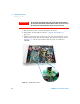
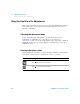
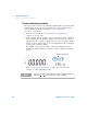
3 Solder a temporary short between the two exposed metal pads on the
main printed circuit (PC) board assembly. The general location is shown
in Figure 6- 1. On the U3606A PC board, the pads are marked as
“SECUR”.
Figure 6-1 SECUR pads location
WARNING
Be careful not to touch the power line connections or high voltages
on the power input module and transformer. Power is present even if
the instrument is turned off when the line cord is connected.