34450A UG.
34450A UG.book Page II Tuesday, July 23, 2013 2:43 PM Notices © Agilent Technologies, Inc. 2012–2013 Warranty No part of this manual may be reproduced in any form or by any means (including electronic storage and retrieval or translation into a foreign language) without prior agreement and written consent from Agilent Technologies, Inc. as governed by United States and international copyright laws.
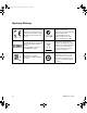
4450A UG.book Page III Tuesday, July 23, 2013 2:43 PM Safety Symbols The following symbols on the instrument and in the documentation indicate precautions that must be taken to maintain safe operation of the instrument. Earth (ground) terminal Caution, risk of electric shock Frame or chassis terminal Caution, risk of danger (refer to this manual for specific Warning or Caution information) CAT II 300 V 34450A User’s Guide IEC Measurement Category II.
34450A UG.book Page IV Tuesday, July 23, 2013 2:43 PM Regulatory Markings IV The CE mark is a registered trademark of the European Community. This CE mark shows that the product complies with all the relevant European Legal Directives. The C-tick mark is a registered trademark of the Spectrum Management Agency of Australia. This signifies compliance with the Australia EMC Framework regulations under the terms of the Radio Communication Act of 1992.
34450A UG.book Page V Tuesday, July 23, 2013 2:43 PM General Safety Information The following general safety precautions must be observed during all phases of operation, service, and repair of this instrument. Failure to comply with these precautions or with specific warnings elsewhere in this manual violates safety standards of design, manufacture, and intended use of the instrument. Agilent Technologies assumes no liability for the customer’s failure to comply with these requirements.
34450A UG.book Page VI Tuesday, July 23, 2013 2:43 PM Protection Limits The Agilent 34450A 5½ Digital Multimeter provides protection circuitry to prevent damage to the instrument and to protect against the danger of electric shock, provided that the Protection Limits are not exceeded. To ensure safe operation of the instrument, do not exceed the Protection Limits shown on the front panel, as defined below: E A B C D Note: The front-panel terminals and current protection fuse are shown above.
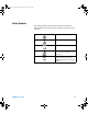
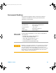
34450A UG.book Page VII Tuesday, July 23, 2013 2:43 PM Environmental Conditions This instrument is designed for indoor use and in an area with low condensation. The table below shows the general environmental requirements for the instrument.
34450A UG.book Page VIII Tuesday, July 23, 2013 2:43 PM Waste Electrical and Electronic Equipment (WEEE) Directive 2002/96/EC This instrument complies with the WEEE Directive (2002/96/EC) marking requirement. This affixed product label indicates that you must not discard this electrical/electronic product in domestic household waste. Product Category: With reference to the equipment types in the WEEE directive Annex 1, this instrument is classified as a “Monitoring and Control Instrument” product.
34450A UG.book Page IX Tuesday, July 23, 2013 2:43 PM Additional Notices The Agilent 34450A is provided with an Agilent 34138A Test Lead Set, described below. Test Lead Ratings Test Leads - 1000 V, 15 A Fine Tip Probe Attachments - 300 V, 3 A Mini Grabber Attachment - 300 V, 3 A SMT Grabber Attachments - 300 V, 3 A Operation The Fine Tip, Mini Grabber, and SMT Grabber attachments plug onto the probe end of the Test Leads. Maintenance If any portion of the Test Lead Set is worn or damaged, do not use.
34450A UG.book Page X Tuesday, July 23, 2013 2:43 PM Declaration of Conformity (DoC) The Declaration of Conformity (DoC) for this instrument is available on the Web site. You can search the DoC by its product model or description. http://regulations.corporate.agilent.com/DoC/search.htm NOTE X If you are unable to search for the respective DoC, please contact your local Agilent representative.
34450A UG.book Page XI Tuesday, July 23, 2013 2:43 PM In This Guide… This guide contains information to install the Agilent 34450A 5½ Digit Multimeter. 1 Getting Started Tutorial This chapter provides a quick tutorial showing you how to get started and use the front panel in order to make measurements. 2 Functions and Features This chapter contains information on the functions and features of the multimeter and how to use the front panel to operate these settings.
34450A UG.book Page XII Tuesday, July 23, 2013 2:43 PM THIS PAGE HAS BEEN INTENTIONALLY LEFT BLANK.
34450A UG.
34450A UG.
34450A UG.
34450A UG.
34450A UG.
34450A UG.
34450A UG.
34450A UG.book Page XX Tuesday, July 23, 2013 2:43 PM Tables THIS PAGE HAS BEEN INTENTIONALLY LEFT BLANK.
34450A UG.book Page 1 Tuesday, July 23, 2013 2:43 PM Agilent 34450A 5½ Digit Multimeter User’s Guide 1 Getting Started Tutorial The Front Panel at a Glance 2 The Keypad at a Glance 6 The Rear Panel at a Glance 10 Feature Upgrades 9 Making Measurements 11 Selecting a Range 24 Remote Operation 25 This chapter provides a tutorial on how to get started using the Agilent 34450A 5½ Digit Multimeter and using the front panel in order to make measurements.
34450A UG.
34450A UG.book Page 3 Tuesday, July 23, 2013 2:43 PM Getting Started Tutorial 1 The display at a glance Single display screen Figure 1-2 Typical single display screen Dual display screen Figure 1-3 Typical dual display screen The system annunciators are described in Table 1- 1. (See Table 2- 2 on page 42 for Math Annunciators).
34450A UG.book Page 4 Tuesday, July 23, 2013 2:43 PM 1 Getting Started Tutorial Table 1-1 Display annunciators System Annunciator Description Sample annunciator - indicates readings being taken The keypad has been locked.
34450A UG.
34450A UG.book Page 6 Tuesday, July 23, 2013 2:43 PM 1 Getting Started Tutorial The Keypad at a Glance The operation for each key is shown in Table 1- 2 below. Pressing a measurement function key changes the current key operation, brings up the relevant symbol on the display (see “The display at a glance” on page 3), and emits a beep.
34450A UG.book Page 7 Tuesday, July 23, 2013 2:43 PM Getting Started Tutorial 1 Table 1-2 Keypad functions (continued) Key > Description • Press to adjust range • Press to adjust values Press to access utility menu.
34450A UG.book Page 8 Tuesday, July 23, 2013 2:43 PM 1 Getting Started Tutorial Table 1-2 Keypad functions (continued) Key Description Measurement - related functions Press to enable null function. See “Null measurement” on page 33 Press to access math functions menu. See “Math Operations” on page 32 Press to access data logging menu. See “Data Logging” on page 65 Press to access store/recall menu. See “Storing and Recalling Instrument States” on page 56 8 > Press to enable trigger/hold.
34450A UG.
34450A UG.
34450A UG.book Page 11 Tuesday, July 23, 2013 2:43 PM Getting Started Tutorial 1 Making Measurements The following pages show how to make measurement connections and how to select measurement functions from the front panel for each of the measurement functions. For remote operation, refer to the MEASure Subsystem in the Agilent 34450A Online Programmer’s Reference Helpfile.
34450A UG.book Page 12 Tuesday, July 23, 2013 2:43 PM 1 Getting Started Tutorial Digit masking The navigation keypad provides a shortcut to mask (change the number of digits displayed) the reading on the main display, easing readability. Masking digits only affects what is displayed. It does not affect measurement speed or accuracy. It applies to all functions except continuity, diode test, temperature, and capacitance measurement.
34450A UG.book Page 13 Tuesday, July 23, 2013 2:43 PM Getting Started Tutorial 1 Selecting current input terminals and measurement range If AC or DC current is being measured in auto- ranging mode, with a signal input at 100 mA, the meter will select the range 100 µA to 100 mA automatically. If a signal input is applied to the 10 A input terminal, the meter will select the 1 A to 10 A range automatically. Measuring AC (RMS) or DC voltage AC Voltage: • • • • Measurement Range: 100.000 mV, 1.00000 V, 10.
450A UG.book Page 14 Tuesday, July 23, 2013 2:43 PM 1 Getting Started Tutorial 1 2-a Typical ACV Measurement Display 3-a AC or DC voltage source 2-b Typical DCV Measurement Display 3-b Figure 1-6 ACV rms and DCV terminal connection and display WA R N I N G 14 Do not apply any voltage to the instrument inputs until all terminals are properly connected. Plugging or unplugging the test lead while high voltage is applied can cause instrument damage, and may increase the risk of electric shock.
34450A UG.book Page 15 Tuesday, July 23, 2013 2:43 PM Getting Started Tutorial 1 Measuring resistance • Measurement Range: 100.000 Ω,, 1.00000 kΩ,, 10.0000 kΩ,, 100.000 kΩ, 1.00000 MΩ, 10.0000 MΩ, 100.000 MΩ.
34450A UG.book Page 16 Tuesday, July 23, 2013 2:43 PM 1 Getting Started Tutorial Measuring AC (RMS) or DC current up to 100 mA • • • • • • Measurement Range (AC): 10.0000 mA, 100.000 mA Measurement Range (DC): 100.000 µA, 1.00000 mA, 10.0000 mA, 100.000 mA Speed (AC): Slow-2 Hz, Medium-20 Hz, Fast-200 Hz Speed (DC): Slow, Medium, Fast Default Setting: Autoranging, Slow measurement speed Shunt Resistance: 1 Ω for 10 mA and 100 mA, and 90 Ω for 100 µA to 1 mA ranges • Input Protection: Rear Panel 0.
34450A UG.book Page 17 Tuesday, July 23, 2013 2:43 PM Getting Started Tutorial 1 Measuring AC (RMS) or DC current up to 10 A • • • • • • • 1 AC or DC Voltage Source Measurement Range (AC): 1.00000 A, 10.0000 A Measurement Range (DC): 1.00000 A, 10.0000 A Speed (AC): Slow-2 Hz, Medium-20 Hz, Fast-200 Hz Speed (DC): Slow, Medium, Fast Default Setting: Autoranging, Slow measurement speed Shunt Resistance: 0.
34450A UG.book Page 18 Tuesday, July 23, 2013 2:43 PM 1 Getting Started Tutorial Measuring frequency for voltage • Measurement Range: 100.000 mV, 1.00000 V, 10.0000 V, 100.000 V, 750.00 V. Range is based on the voltage level of the signal, not frequency. • Speed: Slow, Medium • Measurement Method: Reciprocal counting technique • Signal level: 10% of range to full scale input on all ranges except where noted. 100 mV range specifications are for full scale or greater inputs.
34450A UG.book Page 19 Tuesday, July 23, 2013 2:43 PM Getting Started Tutorial 1 Measuring frequency for current • Measurement Range: 10.0000 mA, 100.000 mA, 1.00000 A, 10.0000 A. Range is based on the current level of the signal, not frequency. • Speed: Slow, Medium • Measurement Method: Reciprocal counting technique • Signal level: 10% of range to full scale input on all ranges except where noted. 10 mA range specifications are for full scale or greater inputs.
34450A UG.book Page 20 Tuesday, July 23, 2013 2:43 PM 1 Getting Started Tutorial Testing continuity • • • • I Measurement Method: 0.5 mA ± 0.
34450A UG.book Page 21 Tuesday, July 23, 2013 2:43 PM Getting Started Tutorial 1 Checking diodes • Measurement Method: Uses 0.5 mA ± 0.
34450A UG.book Page 22 Tuesday, July 23, 2013 2:43 PM 1 Getting Started Tutorial Measuring temperature • Measurement Range: –80.0 °C to 150.0 °C, –110.0 °F to 300.
34450A UG.book Page 23 Tuesday, July 23, 2013 2:43 PM Getting Started Tutorial 1 Measuring capacitance • Measurement Range: 1.000 nF, 10.00 nF, 100.0 nF, 1.000 µF, 10.00 µF, 100.0 µF, 1.000 mF, 10.00 mF • Default Setting: Autoranging • Measurement Method: Computed from constant current source charge time. Typical 0.12 V to 1.
34450A UG.book Page 24 Tuesday, July 23, 2013 2:43 PM 1 Getting Started Tutorial Selecting a Range You can let the multimeter automatically select the range using autoranging, or you can select a fixed range using manual ranging. Autoranging is convenient because the multimeter automatically selects the appropriate range for sensing and displaying each measurement.
34450A UG.
34450A UG.book Page 26 Tuesday, July 23, 2013 2:43 PM 1 Getting Started Tutorial NOTE To easily configure and verify an interface connection between the 34450A and your PC, use the Automation- Ready CD, which is shipped with your 34450A. This CD includes the Agilent IO Libraries Suite and the Agilent Connection Expert application. For more information about Agilent's I/O connectivity software, visit www.agilent.com/find/iolib.
34450A UG.book Page 27 Tuesday, July 23, 2013 2:43 PM Getting Started Tutorial 1 The connecting diagram and setup procedure are shown in “Serial interface connector diagram” and “RS232 utility sub- menu” on page 52 below.
34450A UG.book Page 28 Tuesday, July 23, 2013 2:43 PM 1 Getting Started Tutorial Code compatibility mode The 34450A includes a code compatibility mode. This mode saves time and effort by eliminating the need to re- write programs using the 34450A SCPI command. SCPI commands The Agilent 34450A complies with the syntax rules and conventions of SCPI (Standard Commands for Programmable Instruments).
34450A UG.book Page 29 Tuesday, July 23, 2013 2:43 PM Getting Started Tutorial 1 • You can query the SCPI version from the remote interface only. • The SCPI version is returned in the form “YYYY.V”, where “YYYY” represents the year of the version, and “V” represents a version number for that year (for example, 1994.0).
34450A UG.
34450A UG.book Page 31 Tuesday, July 23, 2013 2:43 PM Agilent 34450A 5½ Digit Multimeter User’s Guide 2 Functions and Features Math Operations 32 The Dual Display 44 Using the Utility Menu 47 Storing and Recalling Instrument States 56 Reset/Power-On State 58 Triggering the Multimeter 60 Data Logging 65 This chapter contains information on the functions and features of the Agilent 34450A 5½ Digit Multimeter and how to use the front panel to operate these settings.
34450A UG.book Page 32 Tuesday, July 23, 2013 2:43 PM 2 Functions and Features Math Operations Table 2- 1 below describes the math operations that can be used with each measurement function.
34450A UG.book Page 33 Tuesday, July 23, 2013 2:43 PM Functions and Features 2 Null measurement When making null measurements, also called relative measurement, each reading is the difference between a stored null value and the input signal. For example, this feature can be used to make more accurate resistance measurements by nulling the test lead resistance.
34450A UG.
34450A UG.book Page 35 Tuesday, July 23, 2013 2:43 PM Functions and Features 2 Hold measurement The hold feature allows you to capture and hold a stable reading on the front panel display. When a stable reading is detected, the multimeter emits a beep (if the buzzer is enabled in the utility menu) and holds the reading on the primary display.
34450A UG.book Page 36 Tuesday, July 23, 2013 2:43 PM 2 Functions and Features Limit measurement The limit operation allows you to perform pass/fail testing against specified upper and lower limits. 1 > Press to enable limit measurements 2 The upper limit must always be greater than the lower limit. Otherwise, “INVALID LIMIT” will be shown. Shows present measurement Limit state Typical limit function display 3 Press to edit 4 Choose the limit mode that you want to change 6-a 5 .
34450A UG.
34450A UG.
34450A UG.
34450A UG.book Page 40 Tuesday, July 23, 2013 2:43 PM 2 Functions and Features Editing dB measurement When enabled, the dB operation computes the dBm value for the next reading, stores the dBm result into the dB Ref register, and immediately produces the following calculation. The first displayed reading is always precisely 000.00 dB. dB = 10 × Log10 [(Reading2/RREF)/0.001 W]–dB Ref 2 1 Press to edit Select dB option 3 Ongoing measurement dB measurement Reference value 0dB to ±120.
34450A UG.book Page 41 Tuesday, July 23, 2013 2:43 PM Functions and Features 2 Editing dBm measurement The logarithmic dBm (decibels relative to one milliwatt) scale is often used in RF signal measurements. The multimeter’s dBm operation takes a measurement and calculates the power delivered to a reference resistance (typically 50, 75, or 600 Ω). The formula used for conversion from the voltage reading is: dBm = 10 × Log10 [(Reading2 / RREF) / 0.
34450A UG.book Page 42 Tuesday, July 23, 2013 2:43 PM 2 Functions and Features Math annunciators Table 2- 2 below shows the possible math annunciators which can appear on the display and the editable values.
34450A UG.book Page 43 Tuesday, July 23, 2013 2:43 PM Functions and Features 2 Editing values For math functions with editable values, the label “PRESS MATH TO EDIT” will be shown at the bottom left of the display.
34450A UG.book Page 44 Tuesday, July 23, 2013 2:43 PM 2 Functions and Features The Dual Display Most measurement functions have predefined range or measurement capabilities that can be displayed in the dual measurement mode. All math operations have predefined operations that are displayed on the dual display. Table 2- 3 below shows the measurement functions which are available in dual display mode.
34450A UG.book Page 45 Tuesday, July 23, 2013 2:43 PM Functions and Features 2 Table 2-4 Measurement operation frequencies for DCV-ACI DCV-ACI Measurement Operation Frequency Slow/Medium >500 Hz (600 Hz) / n x 50 Hz (60 Hz) for <500 Hz Fast >10 kHz / n x 1 kHz for <10 kHz For more information , please refer to Chapter 3, “Measurement Speed Consideration”.
34450A UG.
34450A UG.book Page 47 Tuesday, July 23, 2013 2:43 PM Functions and Features 2 Using the Utility Menu The Utility menu allows you to customize a number of non- volatile instrument configurations. It also displays any SCPI error messages and the latest firmware revision codes.
34450A UG.book Page 48 Tuesday, July 23, 2013 2:43 PM 2 Functions and Features Table 2-5 Utility menu available settings Feature BUZZER Default ON Available Settings Description Remote Command ON or OFF Enables or disables Diode, Stats, Limit, and Hold beep operations. Turning off the buzzer does not disable the front panel keys beep operation and Continuity beep operation. Refer to “The beeper” on page 55 for more info.
34450A UG.book Page 49 Tuesday, July 23, 2013 2:43 PM Functions and Features 2 Table 2-5 Utility menu available settings (continued) CALIBRATION SECURE To secure or unsecure the calibration adjustments to the instrument.
34450A UG.
34450A UG.book Page 51 Tuesday, July 23, 2013 2:43 PM Functions and Features 2 RS232 utility sub-menu To enable the RS232 option, follow the steps below. For a list of RS232 settings, see Table 2- 6 on page 52.
34450A UG.
34450A UG.book Page 53 Tuesday, July 23, 2013 2:43 PM Functions and Features 2 GPIB Utility Sub-Menu To activate GPIB, first, turn on the GPIB option. The following pop- up message will appear if the GPIB license key is not activated : “GPIB is not enabled, to enable, please visit www.agilent.com/find/34450A” If GPIB connectivity is selected, a sub- menu will appear to allow you configure the address (from 0 to 30) for remote communication to a PC.
34450A UG.book Page 54 Tuesday, July 23, 2013 2:43 PM 2 Functions and Features Reading error messages To read error messages from the front panel, perform the following procedures. For remote operation, refer to the SYSTem:ERRor? command in the Agilent 34450A Programmer’s Reference Helpfile.
34450A UG.book Page 55 Tuesday, July 23, 2013 2:43 PM Functions and Features 2 The beeper Normally, the multimeter beeps whenever certain conditions are met (for example, the multimeter beeps when a stable reading is captured in reading hold mode). The beeper is factory set to ON, but may be disabled or enabled manually. • Turning OFF the beeper does NOT disable the front panel keys beep tones.
34450A UG.book Page 56 Tuesday, July 23, 2013 2:43 PM 2 Functions and Features Storing and Recalling Instrument States The present multimeter state, including all settings for measurement configuration, math operation, and system operations, can be saved in one of the six non- volatile memory location and later recalled. Location LAST retains the multimeter configuration at power down. Location LAST and 1- 5 are available for storing the configurations.
34450A UG.
34450A UG.book Page 58 Tuesday, July 23, 2013 2:43 PM 2 Functions and Features Reset/Power-On State The table below summarizes the 34450A settings as received from the factory, following power cycling, and following the *RST command received over the USB remote interface. Non- volatile, user customizable behavioral differences are shown in BOLD.
34450A UG.
34450A UG.book Page 60 Tuesday, July 23, 2013 2:43 PM 2 Functions and Features Triggering the Multimeter At power- on, the default trigger source is auto- triggering. Auto- triggering takes continuous readings at the fastest rate possible for the selected measurement configuration. To make a trigger measurement, follow the steps below: 1 Configure the multimeter for the measurement by selecting the function, range, resolution, and so on. 2 Specify the multimeter’s trigger source.
34450A UG.book Page 61 Tuesday, July 23, 2013 2:43 PM Functions and Features 2 Software (Bus) Triggering The bus trigger mode is available from the remote interface only. The bus trigger mode is initiated by sending a bus trigger command, after selecting BUS as the trigger source. • The TRIGger:SOURce BUS command selects the bus trigger source. • The MEASure? command overwrites the BUS trigger and triggers the DMM and returns a measurement.
34450A UG.book Page 62 Tuesday, July 23, 2013 2:43 PM 2 Functions and Features External Trigger External triggering takes one reading (or the specified number of readings in data logger) each time the multimeter receives a pulse on the rear- panel external trigger connector. The multimeter uses the rising edge (POS) of the external trigger signal to trigger a reading.
34450A UG.book Page 63 Tuesday, July 23, 2013 2:43 PM Functions and Features 2 In data log/external trigger mode, a trigger out signal is sent whenever a measurement is log/triggered and updated on the front panel. In code compatibility mode, a trigger out signal is sent whenever a measurement is updated on the front panel or a measurement is taken by the user using command.
34450A UG.book Page 64 Tuesday, July 23, 2013 2:43 PM 2 Functions and Features measurement. Trigger out and manual trigger implement a standard hardware handshake sequence between measurement and switching devices.
34450A UG.book Page 65 Tuesday, July 23, 2013 2:43 PM Functions and Features 2 Data Logging The data logger feature provides a front- panel interface that allows you to set up data logging into the instrument’s non- volatile memory with programming, and without a connection to a computer. Once you have finished collecting data, you can view it from the front panel, or you can also connect your computer and import the data using the DATA:DATA? NVMEM command.
34450A UG.
34450A UG.book Page 67 Tuesday, July 23, 2013 2:43 PM Functions and Features 2 Table 2-8 Data log menu options Option Available settings Description TRIGGER DELAY 0 to 3600 seconds Delay time between a trigger is initiated and first reading is taken by the data log function. The smallest delay time resolution is 100 µs. SAMPLE INTERVAL 1 to 3600 seconds Delay time between subsequent readings. The smallest resolution is 100 µs.
34450A UG.
34450A UG.book Page 69 Tuesday, July 23, 2013 2:43 PM Functions and Features 2 Viewing the log info Log info page shows the record number of the log data, function, and range for the primary and secondary measurement when data is logged. If no data is available for that log, NA is displayed.
34450A UG.
34450A UG.
34450A UG.
34450A UG.book Page 73 Tuesday, July 23, 2013 2:43 PM Functions and Features 2 Fluke 45/Fluke 8808A Code Compatibility Mode The code compatibility mode enables the user to enter remote commands easily when migrating from one instrument to the next. Enabling the code compatibility function 1 2 > Press to display utility menu Typical log utility menu display 3 Note: RS232 or GPIB connectivity must be enabled in order for the code compatibility mode to work.
34450A UG.book Page 74 Tuesday, July 23, 2013 2:43 PM 2 Functions and Features Notes for Fluke 45/Fluke 8808A code compatibility mode • When the code compatibility function is enabled, the front panel will be in a locked state except the utility menu. • Reset is performed on the multimeter whenever the code compatibility function is turned on or turned off. • Rate is global for every function when the code compatibility mode is enabled.
34450A UG.book Page 75 Tuesday, July 23, 2013 2:43 PM Agilent 34450A 5 ½ Digit Multimeter User’s Guide 3 Measurement Tutorial DC Measurement Considerations 76 Noise Rejection 77 Measurement Speed Consideration 80 Dual Measurement Considerations 81 Resistance Measurement Considerations 84 True RMS AC Measurements 87 Other Primary Measurement Functions 91 Other Sources of Measurement Error 96 The Agilent 34450A multimeter is capable of making very accurate measurements.
34450A UG.book Page 76 Tuesday, July 23, 2013 2:43 PM 3 Measurement Tutorial DC Measurement Considerations Thermal EMF Errors Thermoelectric voltages are the most common source of error in low–level DC voltage measurements. Thermoelectric voltages are generated when you make circuit connections using dissimilar metals at different temperatures. Each metal- to- metal junction forms a thermocouple, which generates a voltage proportional to the junction temperature.
34450A UG.book Page 77 Tuesday, July 23, 2013 2:43 PM Measurement Tutorial 3 Noise Rejection Rejecting Power- Line Noise Voltages A desirable characteristic of integrating analog- to- digital (A/D) converters is their ability to reject power- line related noise present with DC input signals. This is called normal mode noise rejection, or NMR. The multimeter achieves NMR by measuring the average DC input by “integrating” it over a fixed period.
34450A UG.book Page 78 Tuesday, July 23, 2013 2:43 PM 3 Measurement Tutorial Noise Caused by Magnetic Loops If you are making measurements near magnetic fields, take caution to avoid inducing voltages in the measurement connections. You should be especially careful when working near conductors carrying large currents. Use twisted- pair connections to the multimeter to reduce the noise pickup loop area, or dress the test leads as close together as possible.
34450A UG.book Page 79 Tuesday, July 23, 2013 2:43 PM Measurement Tutorial 3 RL HI Ideal Meter Vtest RL LO Ri > 10 G Ω Vground RL = Lead Resistance Ri = Multimeter Isolation Resistance Vground = Voltage Drop on Ground Bus Figure 3-2 Noise caused by ground loops The best way to eliminate ground loops is to isolate the multimeter from earth by not grounding the input terminals. If the multimeter must be earth- referenced, connect it and the device- under- test to the same common ground point.
34450A UG.book Page 80 Tuesday, July 23, 2013 2:43 PM 3 Measurement Tutorial Measurement Speed Consideration There are two methods of integrating the sampled data taken in the measurement, slow/medium (NPLC) and fast (Aperture). When you set the resolution to slow or medium, you can not only achieve improved accuracy associated with time averaging, but also achieve the rejection of the power- line interference (normal mode rejection, or NMR).
34450A UG.book Page 81 Tuesday, July 23, 2013 2:43 PM Measurement Tutorial 3 Dual Measurement Considerations The dual measurements mode allows users to make two measurements in one display. During dual measurement mode, the display will show two separate measurements and there is a switching delay between both measurements.
34450A UG.book Page 82 Tuesday, July 23, 2013 2:43 PM 3 Measurement Tutorial 1.2 V 0V -1.2 V Figure 3-3 ADC Dynamic Range Consider an AC component of 1 Vrms signal with a DC offset of 100 mV. When measuring at DCV 1 V range, Vpeak of the signal is 1.514 V which exceeds the ADC dynamic range of 1.2 V, causing an error in DC measurement. Select a higher range DCV 10 V range for better accuracy. The same error of measurement applies to DCV and ACI dual mode caused by the multimeter’s series burden voltage.
34450A UG.book Page 83 Tuesday, July 23, 2013 2:43 PM Measurement Tutorial 3 Considering the internal resistance and external lead resistance total is 0.0125 ohm. If applying a 1 A DC current, an error of (0.0125 ohm x 1 A) 0.0125 V or 12.5 mV will occur. This error will be relative by range with the ADC dynamic range of 1.2 V. Figure 3-4 Example of measuring voltage and current in dual measurement The error in measurement will be significant when applying a higher current.
34450A UG.book Page 84 Tuesday, July 23, 2013 2:43 PM 3 Measurement Tutorial Resistance Measurement Considerations When measuring resistance, the test current flows from the input HI terminal through the resistor being measured. The voltage drop across the resistor being measured is sensed internal to the multimeter. Therefore, test lead resistance is also measured. The errors mentioned earlier in this chapter for DC voltage measurements also apply to resistance measurements.
34450A UG.book Page 85 Tuesday, July 23, 2013 2:43 PM Measurement Tutorial 3 Table 3-2 Examples of measurement ranges (continued) Range Test Current DUT Power at Full Scale 10 MΩ 100 nA 100 nW 100 MΩ 100 nA / 10 MΩ 1 µW Errors in High Resistance Measurements When you are measuring large resistances, significant errors can occur due to resistance insulation and surface cleanliness. You should take the necessary precautions to maintain a “clean” high- resistance system.
34450A UG.book Page 86 Tuesday, July 23, 2013 2:43 PM 3 Measurement Tutorial Thermal EMF caused by dissimilar metals can create a parasitic voltage in the measurement circuit (VEMF). The thermal EMF can be caused by the input lead connections or internally in resistor R. In general, this voltage will not change with the current applied to the resistor.
34450A UG.book Page 87 Tuesday, July 23, 2013 2:43 PM Measurement Tutorial 3 True RMS AC Measurements True RMS responding multimeters, like the 34450A, measure the “heating” potential of an applied voltage. Power dissipated in a resistor is proportional to the square root of an applied voltage, independent of the waveshape of the signal. This multimeter accurately measures true RMS voltage or current, as long as the wave shape contains negligible energy above the instrument’s effective bandwidth.
34450A UG.book Page 88 Tuesday, July 23, 2013 2:43 PM 3 Measurement Tutorial is a DC voltage content, which is rejected by Agilent’s AC- coupled true rms measurements. This can provide a significant benefit. An AC- coupled true rms measurement is desirable when you are measuring small AC signals in the presence of large DC offsets. For example, this situation is common when measuring AC ripple present on DC power supplies.
34450A UG.book Page 89 Tuesday, July 23, 2013 2:43 PM Measurement Tutorial 3 Notice that crest factor is a composite parameter, dependent upon the pulse- width and repetition frequency; crest factor alone is not enough to characterize the frequency content of a signal. Traditionally, digital multimeters include a crest factor derating table that applies at all frequencies.
34450A UG.book Page 90 Tuesday, July 23, 2013 2:43 PM 3 Measurement Tutorial Table 3-3 Typical errors for various pulse waveforms as a function of input pulse frequency (continued) Typical error for square wave, triangular wave, and pulse trains of CF=3, 5, or 10 prf Square wave Triangle wave CF=3 CF=5 CF=10 50000 –3.41% –0.04% –6.75% –32.0% –65.30% 100000 –5.10% –0.12% –21.8% –50.6% –75.
34450A UG.book Page 91 Tuesday, July 23, 2013 2:43 PM Measurement Tutorial 3 Other Primary Measurement Functions Frequency measurement errors The multimeter uses a reciprocal counting technique to measure frequency. This method generates constant measurement resolution for any input frequency. All frequency counters are susceptible to errors when measuring low- voltage, low- frequency signals. The effects of both internal noise and external noise pickup are critical when measuring “slow” signals.
34450A UG.book Page 92 Tuesday, July 23, 2013 2:43 PM 3 Measurement Tutorial DC current measurements When you connect the multimeter in series with a test circuit to measure current, a measurement error is introduced. The error is caused by the multimeter’s series burden voltage. A voltage is developed across the wiring resistance and current shunt resistance of the multimeter, as shown below.
34450A UG.book Page 93 Tuesday, July 23, 2013 2:43 PM Measurement Tutorial 3 Capacitance measurements The multimeter implements capacitance measurements by applying a known current to the capacitor as shown below: C offset C C offset RP Vcharged Measurement Model (during charge phase) C R' Measurement Model (during discharge phase) Figure 3-6 Applying current to the capacitor Capacitance is calculated by measuring the change in voltage (ΔV) that occurs over a “short aperture” time, (Δt).
34450A UG.book Page 94 Tuesday, July 23, 2013 2:43 PM 3 Measurement Tutorial Range Current Source Reading Rate at Full Scale 1 mF 500 µA 0.25/second 10 mF 1 mA 0.15/second The values of capacitance and loss resistance measured with the multimeter may differ from the values measured using an LCR meter. This is to be expected, since this is essentially a DC measurement method, while LCR measurement uses applied frequencies anywhere from 100 Hz to 100 kHz.
34450A UG.book Page 95 Tuesday, July 23, 2013 2:43 PM Measurement Tutorial 3 Temperature measurements The multimeter measures temperature by measuring the temperature sensitive resistance of 5 kW thermistors. Thermistors consist of semiconductor materials and provide roughly 10 times the sensitivity of an RTD. Because they are semiconductors, their temperature range is more limited, commonly to –80 °C to 150 °C.
34450A UG.book Page 96 Tuesday, July 23, 2013 2:43 PM 3 Measurement Tutorial Other Sources of Measurement Error Loading Errors (AC volts) In the AC voltage function, the input of the multimeter appears as a 1 MW resistance in parallel with 100 pF of capacitance. The cabling that you use to connect signals to the multimeter also adds capacitance and loading.
34450A UG.book Page 97 Tuesday, July 23, 2013 2:43 PM Measurement Tutorial 3 Temperature changes inside the multimeter due to self- heating may cause additional error on other AC voltage ranges. AC Current Measurement Errors (Burden Voltage) Burden voltage errors, which apply to DC current, also apply to AC current measurements. However, the burden voltage for AC current is larger due to the multimeter’s series inductance and your measurement connections.
34450A UG.book Page 98 Tuesday, July 23, 2013 2:43 PM 3 Measurement Tutorial Most extraneous noise is not correlated with the input signal. You can determine the error as shown below. Voltage Measured = Vin2 + Noise 2 Correlated noise, while rare, is especially detrimental. Correlated noise always adds directly to the input signal. Measuring a low- level signal with the same frequency as the local power line is a common situation that is prone to this error.
34450A UG.
34450A UG.book Page 100 Tuesday, July 23, 2013 2:43 PM 4 Specifications Test Considerations These specifications apply when using the 34450A in an environment that is free of electromagnetic interference and electrostatic charge. When using the multimeter in an environment where electromagnetic interference or significant electrostatic charge is present, measurement accuracy may be reduced.
34450A UG.book Page 101 Tuesday, July 23, 2013 2:43 PM Specifications 4 DC Specifications Specifications are for 90 minutes warm- up time, slow mode, and operating temperature within 18 °C – 28 °C Table 4-1 DC accuracy ± (% of reading + % of range) Function DC Voltage Resistance (2-wire) [2] Resistance (4-wire) [2] Input Impedance 1 Year 23 °C ± 5° C Temperature Coefficient 0 °C – 18 °C 28 °C – 55 °C - 10 MΩ or > 10 GΩ 0.018 + 0.008 0.0020 + 0.0008 1.00000 V - 10 MΩ or > 10 GΩ 0.015 + 0.
34450A UG.book Page 102 Tuesday, July 23, 2013 2:43 PM 4 Specifications Table 4-1 DC accuracy ± (% of reading + % of range) (continued) Input Impedance 1 Year 23 °C ± 5° C Temperature Coefficient 0 °C – 18 °C 28 °C – 55 °C Function Range [1] Test Current or Burden Voltage Continuity [3] 1000 Ω 0.5 mA - 0.05 + 0.03 0.005 + 0.005 Diode Test[4] 1.0000 V 0.5 mA - 0.05 + 0.03 0.005 + 0.
34450A UG.book Page 103 Tuesday, July 23, 2013 2:43 PM Specifications 4 AC Specifications Specifications are for 90 minutes warm- up time, slow mode, and operating temperature within 18 °C – 28 °C Table 4-2 AC accuracy ± (% of reading + % of range) Function Range [1] 100.000 mV True RMS AC Voltage [2] 1.00000 V to 750.00 V True RMS AC Current[2] 10.0000 mA to 10.0000 A Frequency 1 Year 23 °C ± 5 °C Temperature Coefficient 0 °C – 18 °C 28 °C – 55 °C 20 Hz – 45 Hz 1.0 + 0.1 0.02 + 0.
34450A UG.book Page 104 Tuesday, July 23, 2013 2:43 PM 4 Specifications Table 4-3 Frequency accuracy ± (% of reading + count) Function Range Frequency 1 Year 23 °C ± 5 °C Temperature Coefficient 0 °C to 18 °C 28 °C to 55 °C Frequency 100.000 mV to 750.00 V [1] 20 Hz – 300 kHz [2] 0.02 + 3 0.005 10.0000 mA to 10.0000 A 20 Hz – 10 kHz [3] 0.02 + 3 0.005 [1] The specifications are using an aperture of 1 second. The frequency can be measured up to 1 MHz as 0.5 V signal to 100 mV or 1 V ranges.
34450A UG.book Page 105 Tuesday, July 23, 2013 2:43 PM Specifications 4 Temperature and Capacitance Specifications Specifications are for 90 minutes warm- up time, slow mode and operating temperature within 18 °C – 28 °C Table 4-5 Temperature and capacitance accuracy ± (% of reading + % of range) Range [1] Probe Type or Test Current 1 Year 23 °C ± 5 °C Temperature Coefficient 0 °C to 18 °C 28 °C to 55 °C –80.0 °C to 150 °C 5 kΩ thermistor probe Probe accuracy +0.2 °C 0.002 °C –110.0 °F to 300.
34450A UG.book Page 106 Tuesday, July 23, 2013 2:43 PM 4 Specifications Operating Specifications Table 4-6 Operating specifications on single display (approximate) Function ACV DCV 2-Wire Ω 4-Wire Ω Frequency [5] ACI DCI 106 Reading Rate /sec[4] Function Change (sec)[1] Range Change (sec)[2] Auto Range (sec)[3] USB GPIB Serial Slow (5.5) 2.6 2.5 4.6 1.9 1.9 1.9 Med (4.5) 1.2 1.2 1.5 19 19 19 Fast (4.5) 1.1 1.1 1.2 160 99 33 Slow (5.5) 1.3 1.3 1.6 1.7 1.7 1.
34450A UG.book Page 107 Tuesday, July 23, 2013 2:43 PM Specifications 4 Table 4-6 Operating specifications on single display (approximate) (continued) Function Resolution Reading Rate /sec[4] Function Change (sec)[1] Range Change (sec)[2] Auto Range (sec)[3] USB GPIB Serial Diode 4.5 0.1 - - 190 117 38 Continuity 4.5 0.1 - - 165 111 33 Temperature 4.5 0.5 - - 4.2 4.
34450A UG.book Page 108 Tuesday, July 23, 2013 2:43 PM 4 Specifications Supplemental measurement specifications Table 4-7 Supplemental measurement specifications DC Voltage • Measuring Method: • Sigma Delta A-to-D converter • Input Resistance: • >10 GΩ ± 2% range (Selectable 100 mV, 1 V ranges) • 10 MΩ ± 2% range (typical) • Input Protection: • 1000 V on all ranges (HI terminal) Resistance • Measurement Method: • 2-wire or 4-wire Ohms • Open-Circuit Voltage • Limited to < 2.
34450A UG.book Page 109 Tuesday, July 23, 2013 2:43 PM Specifications 4 Table 4-7 Supplemental measurement specifications (continued) Continuity / Diode Test • Measurement Method: • Uses 0.5 mA ± 0.
34450A UG.
34450A UG.book Page 111 Tuesday, July 23, 2013 2:43 PM Specifications 4 Table 4-7 Supplemental measurement specifications (continued) • Input Protection: • 750 V rms on all ranges (HI terminal) Math Functions • Null, dBm, dB, Min/Max/Avg, Hold, Limit Test Data Log • Info, List, Histrogram Triggering and Memory • Samples per Trigger: 1 to 5,000 (typical) ,1 to 50,000 (optional) • Trigger Delay: 0 to 3600 sec (100 µs step size) Trigger Out • 3.
34450A UG.
34450A UG.book Page 113 Tuesday, July 23, 2013 2:43 PM Specifications 4 Table 4-8 General characteristics Shock and Vibration • Tested to IEC/EN 60086-2 Dimension (H×W×D) • Rack: 88.5 mm × 212.6 mm × 272.3 mm • Bench: 103.8 mm × 261.1 mm × 303.2 mm Weight • 3.75 kg (8.27 lb.
34450A UG.book Page 114 Tuesday, July 23, 2013 2:43 PM 4 Specifications To calculate total measurement error The multimeter’s accuracy specifications are expressed in the form: ( % of reading + % of range ). In addition to the reading error and range error, you may need to add additional errors for certain operating conditions. Check the list below to make sure you include all measurement errors for a given function.
34450A UG.book Page 115 Tuesday, July 23, 2013 2:43 PM Specifications 4 Accuracy specifications Transfer Accuracy Transfer accuracy refers to the error introduced by the multimeter due to noise and short-term drift. This error becomes apparent when comparing two nearly-equal signals for the purpose of “transferring” the known accuracy of one device to the other. 1-Year Accuracy These long-term accuracy specifications are valid at the calibration temperature (Tcal) ± 5 °C temperature range.
34450A UG.book Page 116 Tuesday, July 23, 2013 2:43 PM 4 Specifications Configuring for highest accuracy measurements The measurement configurations shown below assume that the multimeter is in its power-on or reset state. It is also assumed that auto- ranging is enabled to ensure proper full scale range selection. • Select slow mode for 5½ digits. • Null the test lead resistance for 2-wire ohms measurements, and remove any interconnection offset for DC voltage measurements.
34450A UG.book Page 117 Tuesday, July 23, 2013 2:43 PM www.agilent.