
User`s guide


84 34450A Users Guide
3 Measurement Tutorial
Resistance Measurement Considerations
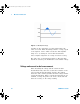
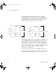
When measuring resistance, the test current flows from the
input HI terminal through the resistor being measured. The
voltage drop across the resistor being measured is sensed
internal to the multimeter. Therefore, test lead resistance is
also measured.
The errors mentioned earlier in this chapter for DC voltage
measurements also apply to resistance measurements.
Additional error sources unique to resistance measurements
are discussed here.
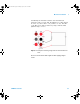
Removing Test Lead Resistance Errors
To eliminate offset errors associated with test lead
resistance, refer to “Null measurement” on page 33
Minimizing Power Dissipation Effects
When measuring resistors designed for temperature
measurements (or other resistive devices with large
temperature coefficients), be aware that the multimeter will
dissipate some power in the device- under- test (DUT).
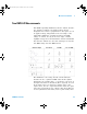
If power dissipation is a problem, you should select the
multimeter’s next higher measurement range to reduce the
errors to acceptable levels. The following table shows several
examples.
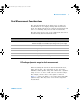
Table 3- 2 Examples of measurement ranges
Range Test Current DUT Power at Full Scale
100 Ω 1 mA 100 µW
1 kΩ 0.5 mA 250
µW
10 kΩ
100
µA
100
µW
100 kΩ
10
µA
10
µW
1 MΩ 1
µA1 µW
34450A UG.book Page 84 Tuesday, July 23, 2013 2:43 PM