
Technical data

Source Total Jitter Tests 4
U7232A DisplayPort Compliance Testing Notes 35
Total Jitter Differential Test
To evaluate the total jitter accompanying the data transmission at either
an explicit bit error rate of 10
-9
or through an approved estimation
technique. This measurement is a data time interval error (Data- TIE) jitter
measurement. (Reference: Table 3.13 VESA DisplayPort Standard)
The overall system jitter budget allocates different amounts of jitter which
each component of the system is allowed to contribute. To exceed any of
these limits is to violate the component level jitter budget. (Reference:
Jitter model in base DisplayPort Specification (Section 3.5.3.9: The Dual
Dirac Jitter Model)
The test must use a PRBS7 test pattern at all voltage levels. The test can
be performed with pre- emphasis for best performance results.
Test P ro ce du re
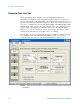
1 Start the automated testing application as described in “Starting the
DisplayPort Electrical Performance Compliance Test Application" on
page 18.
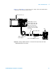
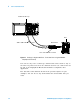
2 Connect the W2641A test fixture to the device under test (DUT).
3 If you are using one connection, connect the probe to any channel. If
you are using two connections, connect the two probes to any two
channels of the oscilloscope. If you are using four connections, connect
the four probes to any four channels of the oscilloscope.
4 Connect the SMA to SMP cable to the SMA probe head of one of the
probes and to the data lane connector on the W2641A fixture that you
want to test.
5 Connect the other SMA to SMP cable to the other SMA probe head and
to the data lane on the W2641A test fixture that you want to test.
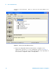
6 In the DisplayPort Compliance Test Application, click the Set Up tab.
7 Set the DUT Definition Driven Setting, the Test Type, the Fixture Type,
Lane- Channel Selection, Connection Settings, and the Connection Type
according to the type of testing being done.