
Specifications


14
DisplayPort Test Point Adapters
DisplayPort has recently added other
connector forms in addition to the
original standard connector. These
include the Mini-DP connector (mDP)
and most recently the eDP connector
(in 20, 30, 40 and 50 pin versions),
and Mobility DisplayPort, a variant for
portables, referred to as MyDP. The
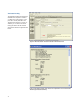
DisplayPort Electrical Performance
Validation and Compliance software
allows you to choose the test point
adapter you want and if the file is
available from the vendor, it lets you
de-embed it as well.
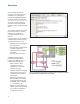
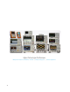
The W2641B DisplayPort TPA test
fixture simplifies the measurement
process by providing access to the
electrical measurement points required
for compliance tests. It breaks out the
DisplayPort data lanes to pairs of SMP
connectors for high-bandwidth probing
with either direct connection to front
panel scope channels, or to InfiniiMax
SMA differential probes through
short SMP-to-SMA cables. To support
DisplayPort AUX Channel for device
control, the AUX lines can be jumpered
to a DisplayPort connector for cable
connection to an AUX Channel
Controller. For Physical Layer AUX
channel testing required for CTS 1.1a
and beyond, four sections are available
to verify signal level and termination
impedance.
DisplayPort AUX channel control
The DisplayPort specification allows
for automated device control through
manipulation of the DPCD (DisplayPort
Configuration Data) registers. Those
registers are most conveniently
controlled by an AUX channel controller.
The choice of AUX channel controllers
is shown in the ordering information
section.
Figure 20. The Agilent W2641B DisplayPort test point adapter fixture
W2621B DisplayPort Test Point Adapter
Measurement requirements
To use the DisplayPort Electrical
Performance Validation and
Compliance software with any test
point adaptor you will need the cables
and other sundry components. The
Agilent W2641B DisplayPort TPA
fixture comes with four right angle
SMP to SMA phase matched cable
pairs and jumper cables as well for the
AUX sections. Use of differential probe
amplifiers and appropriate SMA probe
heads is optional. However, if you
want connection simplicity, consider
these probes for one-time setup and
complete characterization for all
differential measurements.
You can minimize reconnect time by
using four InfiniiMax probes to measure
all four Main Link differential data lanes
(Lane0, Lane1, Lane2, Lane3) without
having to reposition or reconnect
probes. To use this capability, select
Connection Type: Differential Probe,
Number of Channels: Four Channels in
the Setup screen.
If you are not using the W2641B
test fixture, you can still use the
DisplayPort Electrical Performance
Validation and Compliance software
but you will need to consider the
connection to the oscilloscope. If
other test point adaptors are used,
connectivity kits including phase
matched 1 meter SMA cables and
adaptor board for manual hot plug or
automation will be required. If you
are not using a Test point adaptor
but probing signals with solder in
differential probes or browsers then
you will need to select the appropriate
probe head for the task and the probe
amplifier system you are using. For
instance, if the high speed signals are
only accessible through a terminated
50-ohm transmission line (for testing
silicon devices for example), you
will need to use solder-in differential
probe heads for differential probing
and select these in the scope channel
setup menu.