
Specifications


5
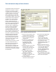
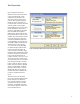
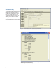
Upon completion of the device
definition, the Test Connection Setup
screen is presented. This screen
enables entry of parameters that
affect the connection of the device
to the oscilloscope. Specifically, the
fixture, the type of connection and
number of lanes connected. The fixture
selection enables not only Agilent
fixture (W2641), but any of the current
fixtures provided by various fixture
vendors as well. While the de-embed
files are available for the Agilent
W2641 fixture, the other fixtures will
have de-embed files as they are made
available. The Connection Type relates
to how the signal gets to the scope
channel. If by differential probe, then
a probe amplifier is assumed (such as
the 1169A or 2800A) and the operator
will then have the choice of using
1,2 or 4 channels of test (depending
on whether the appropriate number
of lanes has been selected). If the
Connection Type is selected is single-
ended then each differential lane of the
test device will have two connections
to the scope. By default these are
routed to channels 1 and 3, or 2 and 4.
This means only two maximum lanes
may be tested this way at a time. Note:
if the Test Type selection in the Start
Project screen was ‘Both’ or ‘Single-
Ended’, then the Connection Type will
default to ‘Single ended’ and will be
grayed out. The number of channels
allowed will always be aware of the
upstream selections so will limit the
number of channels based those
inputs.
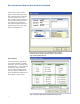
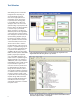
The final screen in the Test Setup
loop is the Channel Assignment Setup
(shown in Figure 5). It will portray
the connection expected in number
of channels and type of connection
requested. It is editable and if there
are channel assignment conflicts, the
user is alerted to the fact.
Test Connection
Figure 4: DisplayPort EPVC software Test Connection Setup Screen