
Specifications


7
Configurability and Guided Connections
Configurability and Guided
Connections
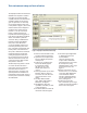
The DisplayPort Electrical Performance
Validation and Compliance software
provides flexibility in your test setup.
It guides you to make connection
changes with hookup diagrams when
the tests you select require it. For
test parameters such as bandwidth,
you can select appropriate values. For
more critical parameters, such as mask
scaling option or number of edges for
analysis, default values are tied to the
compliance standard; these values can
only be altered in the debug screen.
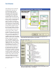
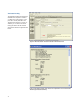
In Figure 7 you can see the selection
for various eye mask test functions.
The default for compliance mode is
“Fixed” which places the mask in the
center of the eye per the DisplayPort
Compliance test specification (shown
is ‘Find Margin,’ which will find the
range of passing conditions).
Note: For HBR2 the eye diagram
testing is different from RBR and HBR
as it comprehends 10
–9
BER limits;
so the ‘Find Margin’ capability is not
available.
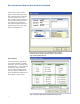
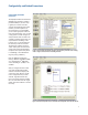
After you configure the test to meet
your needs, the DisplayPort EPVC
software user interface displays the
connection screen, which is specific
to the configuration data you have
selected. Figure 8 illustrates the
typical connection guidance provided
for a one channel “A minus B” single-
ended connection model for a one lane
test setup.
Figure 8. The final step before test is to illustrate the anticipated connection for the test.
Figure 7. The Configure Tab enables changing measurement parameters in the ‘Debug’
mode to support characterization and debug activities.