
User`s guide

122
Triggering Examples
Cross-Arming Trigger Examples
To detect a glitch
The following setup uses a state analyzer to capture state flow
occurring at the time of the glitch. This can be useful in
troubleshooting. For example, you might find that the glitch is ground
bounce caused by a number of simultaneous signal transitions.
1 Set up a timing analyzer and a state analyzer.
2 Go to the timing analyzer's Format menu and set the Timing
Acquisition Mode to Half Channel 500 MHz.
3 Go to the timing analyzer's Trigger menu.
4 Select an Edge term. Then assign glitch detection "*" to the
channels of interest represented by the Edge term.
5 Go to the state analyzer's Trigger menu.
6 Set the analyzer to be armed by the timing analyzer. Leave the
trigger set to trigger on any state.
If you don't see the activity of interest in the state trace, try changing
the trigger position using the Acquisition Control field in the Trigger
menu of the state analyzer. By changing the Acquisition mode to
manual, you can position the trigger at any state relative to analyzer
memory.
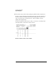
NOTE: The timing analyzer can detect glitch activity on a waveform. A glitch is
defined as two or more transitions across the logic threshold between adjacent
timing analyzer samples.