
User`s guide

219
Using the Pattern Generator
Building Test Vectors and Functions
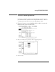
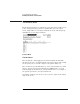
Clock Period (internal clock source)
This field toggles from Clock Period, when an internal clock source is
selected, to Clock Frequency, when an external clock source is
selected.
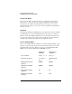
You select clock periods in steps of 1, 2, 2.5, 4, 5, 8, and 10. If the
keypad is used to select a value between the step intervals, the value is
rounded to the nearest interval.
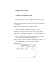
The minimum clock period available with Vector Output Mode at Full
Channel 100 Mbit/s is 10 ns. The minimum clock period available with
Vector Output Mode at Half Channel 200 Mbit/s is 5 ns. Maximum clock
period for either mode is 250 ms.
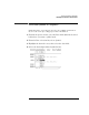
Clock Frequency (external clock source)
This field toggles from Clock Frequency, when an external clock source
is selected, to Clock Period, when an internal clock source is selected.
Set the clock frequency range to match the frequency of the external
clock source.
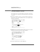
If the Vector Output Mode is Full Channel 100 Mbit/s, you are offered
two clock frequency ranges:
• Less than 50 MHz
• Between 50 MHz and 100 MHz
If the Vector Output Mode is Half Channel 200 Mbit/s, you are offered
three clock frequency ranges:
• Less than 50 MHz
• Between 50 MHz and 100 MHz
• Greater than 100 MHz
NOTE: If the external clock is faster than the frequency range selected, the pattern
generator will produce erroneous output vectors.