
User`s guide

220
Using the Pattern Generator
Building Test Vectors and Functions
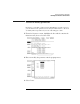
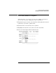
Clock Out Delay
The Clock Out Delay setting allows you to position the output clock
with respect to data. The zero setting is uncalibrated and should be
measured to determine the initial position with respect to the data.
Each numerical change of one on the counter results in an approximate
change of 1.3 ns.
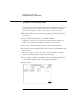
Symbols
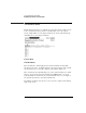
Touching the Symbols field brings up a pop-up menu that lets you build
a symbol table to use when putting data into the Sequence and User
Macros menus. Providing symbol names to frequently used values lets
you enter the values more easily and recognize these values by their
symbol name rather than having to remember data values.
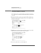
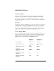
Vector Output Mode
The Vector Output Mode determines the channel width, available pods,
and the frequency range for both the internal and external clock. The
following table shows the difference between the Full Channel 100
MBits/s mode and the Half Channel 200 MBits/s mode.
Full Channel
100 MBits/s
Half Channel
200 MBits/s
Pods Available Pods 1, 2, 3, 4 Pods 1, 3
Maximum Channels 32; eight per
pod
16; eight on pods
1, 3
Maximum External Clock
Frequency
100 MHz 200 MHz
Maximum Internal Clock
Frequency
100 MHz 200 MHz
Minimum External Clock
Frequency
DC DC
Minimum Internal Clock
Frequency
4 kHz 4 kHz