
User`s guide

252
Logic Analyzer Reference
Probing
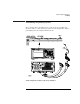
Probe and Pod Grounding
Each pod is grounded by a long, black, pod ground lead. You can
connect the ground lead directly to a ground pin on your target system
or use a grabber. To connect the ground lead to grounded pins on your
target system, you must use 0.63-mm (0.025-in) square pins, or use
round pins with a diameter of 0.66 mm (0.026 in) to 0.84 mm (0.033
in). The pod ground lead must always be used.
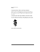
Each probe can be individually grounded with a short black extension
lead that connects to the probe tip socket. You can then use a grabber
or the grounded pins on your target system in the same way you
connect the data lines. For extra confidence in your measurements,
grounding every third or fourth probe is recommended.
When probing signals with rise and fall times of 1 ns or less, grounding
each probe lead with the 2-inch ground lead is recommended. In
addition, always use the probe ground on a clock probe.
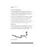
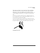
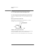
Probe Leads
The probe leads consists of one 12-inch twisted-pair cable, one ground
tap, and one grabber. The probe lead, which connects to the target
system, has an integrated RC network with an input impedance of 100k
ohms in parallel with approximately 1.5-pF. The probe lead has a two-
pin connector on one end that snaps into the probe housing.
Probe Ground Lead