
User`s guide

253
Logic Analyzer Reference
Probing
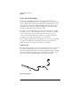
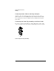
Grabbers
The grabbers have a small hook that fits around the IC pins and
component leads. The grabbers have been designed to fit on adjacent
IC pins on either through-hole or surface-mount components with lead
spacing greater than or equal to 0.050 inches.
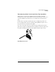
Probe Cable
The probe cable contains 18 signal lines, 17 chassis ground lines and
two power lines for analysis probe use. The cables are woven together
into a flat ribbon that is 4.5 feet long. The probe cable connects the
logic analyzer to the pods, termination adapter, or analysis probe. Each
cable is capable of carrying 0.33 amps for analysis probe power.
CAUTION: DO NOT exceed 0.33 amps per cable, or the cable will be damaged.
Analysis probe power is protected by a current limiting circuit. If the
current limiting circuit is activated, the fault condition must be
removed. After the fault condition is removed, the circuit will reset in
one minute.
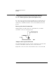
Minimum Signal Amplitude
Any signal line you intend to probe with the logic analyzer probes must
supply a minimum voltage swing of 500 mV to the probe tip. If you
measure signal lines with a voltage swing of less than 500 mV, you may
not obtain a reliable measurement. Because the minimum input
overdrive is the greater of 250 mV or 30% of input amplitude, be sure
to correctly set the pod threshold in the Analyzer Format menu.