
User`s guide


414
Logic Analyzer Concepts
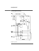
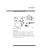
The Analyzer Hardware
ADC Hybrid. The ACD Hybrid provides all of the sampling, digitizing,
and high-speed waveform storage. The ADC includes a phase-locked
loop frequency converter that, for sample rates from 250 MHz to
2 GHz, multiplies the input clock from the time base.
FISO memory. 32,768 samples of the FISO (fast in, slow out) memory
are used per measurement per channel. Memory positions are not
addressed directly. The configuration is a ring which loops
continuously as it is clocked. Memory position is tracked by counting
clocks. The clocking rate is the same as the ADC, however the clock
frequency is half that of the ADC since the FISO clocks on both
transitions of the clock period. Data is buffered onto the CPU data bus
for processing.
Triggering. There are two main trigger circuits that control four
trigger sources. The two trigger circuits are the analog trigger and the
logic trigger. The analog trigger IC operates as a multichannel Schmidt
trigger/comparator. A trigger signal (a copy of the analog input signal)
from each of the inputs (channel 1 and channel 2) is directed to the
analog trigger IC inputs. The trigger signal is continuously compared
with the trigger reference level selected by the user. Once the trigger
condition is met, the trigger true signal is fed to the logic trigger, which
begins the acquisition and store functions by way of the time base.
The four trigger sources are Channel 1, Channel 2, Intermodule Bus
(IMB), and external BNC. Channel 1 and channel 2 triggers were
discussed previously. The IMB trigger signal is sent directly to the logic
trigger. External triggering is provided by the BNC input of the 1670G-
series logic analyzers with the oscilloscope option.
Time base. The time base provides the sample clocks and timing
necessary for data acquisition. It consists of the 100 MHz reference
oscillator and time base hybrid.