XZ001 AGILENT ACQIRIS USER MANUAL FAMILY OF 8-BIT DIGITIZERS For Use with DP and DC Series Digitizers Models covered: DP105 / DP106 / DP110 DP111 / DP210 / DP211 / DP212 DP214 / DP235 / DP240 DP1400 DC110 / DC135 / DC140 DC211 / DC211A / DC240 / DC241 / DC241A DC265 / DC270 / DC271 / DC271A / DC271AR User Manual: Family of 8-bit Digitizers ZM020010I Rev.
June 2007 The information in this document is subject to change without notice and may not be construed in any way as a commitment by Agilent Technologies Inc. While Agilent Technologies makes every effort to ensure the accuracy and contents of the document it assumes no responsibility for any errors that may appear. All software described in the document is furnished under license. The software may only be used and copied in accordance with the terms of license.
CONTENTS 1. OUT OF THE BOX........................................................................................................................... 5 1.1. Message to the User ..................................................................................................................... 5 1.2. Using this Manual ........................................................................................................................ 5 1.3. Conventions Used in This Manual ................................
3.4.3. Trigger Level.................................................................................................................. 35 3.4.4. Edge Trigger Slope......................................................................................................... 35 3.4.5. Window Trigger ............................................................................................................. 35 3.4.6. HF Trigger........................................................................................
1. Out of the Box 1.1. Message to the User Congratulations on having purchased an Agilent Technologies Acqiris data conversion product. Acqiris Digitizers are high-speed data acquisition modules designed for capturing high frequency electronic signals. To get the most out of the products we recommend that you read this manual carefully. We trust the product you have purchased will meet with your expectations and provide you with a high quality solution to your data conversion applications. 1.2.
DC271-FAMILY 1.4. DC135/DC140/DC211/DC211A/DC241/DC241A/ DC271/DC271A/ DC271AR/DP214/DP235/DP240 Disclaimer and Safety The DP Series PCI Digitizer cards have been designed to operate in a standard PCI slot found inside most personal computers. The model DC Series CompactPCI/PXI Digitizers have been designed to operate inside a CompactPCI/PXI crate. The crate provides the modules with all needed power.
1.7. Warranty All Agilent Technologies Acqiris Digitizer products are warranted to operate within specification, assuming normal operation, for a period of three years from the date of shipment. It is recommended that yearly calibration be made in order to verify product performance. All repairs, replacement and spare parts are warranted for a period of 3 months. A 5-year repair warranty is available as an option.
Linux kernel driver source code is available for compilation. Support for Windows 95/98/NT4 is included “as is” since these operating systems are no longer supported by Microsoft. Hard Drive Space: 20 MB Minimum CD Drive (or any method to copy Acqiris Software installation files from CD to the hard drive such as LAN, floppy drive, etc.) LabVIEW: The Acqiris LabVIEW driver is available for National Instruments LabVIEW versions 7.1or 8.
1.12. Cleaning Cleaning procedures consist only of exterior cleaning. Clean the exterior surfaces of the module with a dry lint-free cloth or a soft-bristle brush. If any dirt remains, wipe with a cloth moistened in a mild soap solution. Remove any soap residue by wiping with a cloth moistened with clear water. Do not use abrasive compounds on any parts. 1.13. Disposal and Recycling Electronic equipment should be properly disposed of.
2. Installation This chapter describes how to install the Acqiris hardware and software for Windows 2000/XP, National Instruments LabVIEW RT, Linux, or Wind River VxWorks. NOTE: For a first time installation we strongly recommend installing the software before inserting the hardware into the PC. 2.1. IC414 Installation NOTE: If you are going to install an IC414 interface for the first time and are running Windows 2000/XP you should follow the procedure below before installing the Acqiris hardware. 2.
The PCI-8570/PXI-8570 User's Manual (Rev. 1.00) section 2.4 contains the software installation instructions. These should be executed before allowing the hardware installation process to look for the driver. If you have an AdLink CD Version 2004A4 or later you can use it; if not you should download the latest driver from the WEB site (http://www.adlinktech.com/). You can then continue with the Hardware Installation. A reboot will then be necessary.
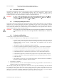
3. To proceed with the installation click “Next”. The following screen will be shown. 4. Please enter your user information and click “Next” to continue. If the program finds that there is still Acqiris software installed on your machine a warning panel (not shown) will appear.
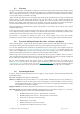
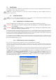
5. Pick the desired combination of module families and click "Next" to continue. 6. The screen above will normally allow the documentation to be installed. Remove the check from the box if you do not want online access to the manuals. 7. The next screen allows you to enable LabVIEW RT and/or Wind River VxWorks support. By default there will be none but if desired you can install any of them together with Windows support or without Windows support. Click “Next” to continue.
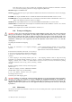
8. The screen below asks for the desired installation type. After having made your choice Click “Next” to continue. 9. If you chose the Custom installation, the following screen will let you select each package individually. Note that the space indicated for LabVIEW, Firmware and UserManual packages is incorrect. The correct values are 4.1 MB, 21 MB, and 27 MB respectively.
10. If MATLAB is installed on your machine, you will be asked to point the installer to the MATLAB root directory. You should do this if you want the installer to modify the standard startup.m file to incorporate the Acqiris adaptor. 11. Now that the elements of the installation have all been decided you will be prompted for the installation folder. This will be the root directory of the Acqiris software installation.
13. If you have enabled the installation of 12-bit Digitizers, Averagers, or Analyzers, the next screen lets you change the name of the directory where the FPGA firmware will be installed. 14. AcqirisLive needs the LabWindows/CVI 7.0 Run-Time Engine to run. If Setup has detected that a LabWindows/CVI Run-Time Engine is already installed on your system, it will ask you if you would like to install it locally for AcqirisLive anyway.
15. Depending on the install type, you may be asked which LabVIEW version format you want for the LabVIEW files. Select the appropriate format and click “Next” to continue. 16.
17. You are now ready to install. You may still go back to any previous screen to modify your selection. Click “Install” when ready. 18. Setup will now copy the files and make the necessary changes to your system. When done, an information screen will be displayed. Please read this carefully.
. Registration of your installation will help us provide you with better support. You will also be notified of updates and upgrades. All information submitted to us will be treated confidentially and never be disclosed outside the company.
. Setup will prepare a registration e-mail in your e-mail client application upon termination of the setup procedure. You can then decide whether or not you wish to send it. You may also add comments. Uncheck the box if you do not want to register your installation. 21. Click “Finish”. The software installation is now complete. 22. You can now either accept the suggestion to restart the computer or you should shutdown your computer and proceed with the hardware installation.
2.3. Installing the Software for Linux The Acqiris Software is ready to install and run on Linux systems with any of the following: RedHat Enterprise Linux Version 3 - Kernel Version 2.4.21-4.EL RedHat Enterprise Linux Version 3 - Kernel Version 2.4.21-4.ELsmp, Suse Linux 9.2 - Kernel version 2.6.8-24-smp, Debian Sarge 3.1 2.6.8-3-686, Debian 4.0 etch Kernel version 2.6.18-4-686, Scientific Linux 4.4 Kernel version 2.6.9-11.
acqrsPCI.o.2.4.21-4.EL acqrsPCI.ko.2.6.8-3-686 acqrsPCI.ko.2.6.8-24-smp acqrsPCI.ko.2.6.9-11.EL acqrsPCI.ko.2.6.18-4-686 for Red Hat Enterprise Linux version 3 for Debian 3.1 'sarge' for Suse 9.2 for Scientific Linux 4.4 for Debian 4.0 'etch' To install the driver and the load script to the system, you have to get super user privileges and execute the driver install script by typing, cd AcqirisLinux ./drv-install add You can check that the driver is loaded properly with lsmod or dmesg.
2.3.2. Special cases If you are running a Linux distribution that doesn’t use the standard paths for the load scripts, you can load the driver with the command cd AcqirisLinux ./drv-install load Copy the driver to the module directory as follows: cp lib/modules/acqrsPCI.o[.n] /lib/modules/{kv}/ACQIRIS/acqrsPCI.o where [.n] is the optional designation of the desired version of the acqrsPCI driver as given above and {kv} is the appropriate system kernel version (obtained with uname -r, i.e. 2.4.20).
3. Turn on the power of the crate(s), if present, and then the PC and start the operating system. NOTE: Acqiris Digitizers are equipped with a LED. If this LED is not glowing orange or red when the power is applied there is a severe problem. Either the module is broken or the necessary voltages for its use are not available.
To proceed with the installation click "No, not this time" and then “Next”. The following window will appear: To proceed with the installation click “Next”.
and then NOTE: In some systems an application program (such as AcqirisLive) will not yet work correctly at this point. One additional boot cycle may be needed if this is the first time that a hardware board is being installed. 2.6. LabVIEW RT During program development you can choose whether you use LabVIEW or LabVIEW RT compatible libraries by switching the version present in National Instruments\LabVIEW m.n\instr.lib\.
using the Install VI library for LabVIEW or LabVIEW Real-Time shortcut available in the Shortcut folder under Start → Programs. There is only one Acqiris Driver. It supports all Acqiris Instruments. The instructions below concern LabVIEW RT as used in NI PXI processors. The Aq_RT.inf and AqRT_4.ini files must be uploaded to the target. To do this, • start the MAX application, • right click on the target • select file transfer • select the Aq_RT.
3. Product Description 3.1. Overview DP110 Block Diagram Signal Input 8bit 8 bit Input Signal Amplifier 50 Ohms SH + ADC Ext memories DEMUX Acq Mem 1M Ohms TIMEBASE trigger Input Trigger Signal Amplifier 50 Ohms TRIGGER circuit Thr DAC 1M Ohms CAL DAC Card Controller Controller PLX PCI Interface PCI Bus Acqiris Digitizers are available in two popular industry standards. The DP series digitizers are PCI modules that plug directly into a vacant PCI slot in a PC.
3.2. Channel Input 3.2.1. Coupling Both AC and DC coupling modes are available. The AC mode couples signals capacitively thus removing the input signal’s DC component and filtering out any signal component below 16 Hz for the DC2x1A digitizers, 32 Hz for the DC271-Family and 10 Hz for all other models. DC mode allows all signal components to be passed through to the digitizer. 3.2.2. Impedance The input channels of the DP and DC Series digitizers offer termination into 50 Ω and, sometimes 1 MΩ.
Model Agilent # DP105 Bandwidth into 50 Ω Bandwidth/ Capacitance into 1 MΩ Minimum Rise Time BW Limiter selections Maximum Offset Other particularities 150 MHz 150 MHz 2.3 ns NA 20 V BW50 = 90 MHz 8 pF U1067A DP106 250 MHz NA 1.4 ns NA NA BW50 = 200 MHz Max FS =0.5 V DP110 250 MHz 250 MHz 1.4 ns NA 20 V BW50 = 200 MHz 8 pF U1067A DP111 500 MHz NA 0.7 ns 25 MHz NA BW50 = 200 MHz Max FS =0.5 V DP210 500 MHz 400 MHz 0.
Model Agilent # DC241A U1064A DC265 Bandwidth into 50 Ω Minimum Rise Time BW Limiter selections Maximum Offset Other particularities 950 MHz ( 1 GHz typical) Bandwidth/ Capacitance into 1 MΩ 300 MHz typical 14 pF 0.35 ns (50Ω) (1.2 ns typical 1 MΩ) 20, 200, 700 MHz (see remark below) 5 V (50Ω) DC271 FAMILY Max FS = 50 V (1 MΩ) 150 MHz 150 MHz 2.3 ns NA 20 V BW50 = 90 MHz 1.4 ns NA 20 V BW50 = 90 MHz 11 pF U1063A DC270 250 MHz 250 MHz 11 pF U1063A DC271 20 V (> 0.
3.2.9. Using Probes The 50 Ω and 1 MΩ input impedance settings make it possible to use Acqiris digitizers with a wide variety of probes. The 50 Ω setting is most commonly used for active probes and low impedance (500 Ω) passive probes. The 1 MΩ setting is normally used for high impedance probes. While it is possible to use a variety of different manufacturers high impedance probes we recommend the use of our model P001 Passive Probe.
The * indicates a Dual Input module where there is one channel which can digitize the signal on one of the two BNC inputs 3.3.1. Sampling Rate All Acqiris digitizers contain an analog-to-digital conversion (ADC) system that can sample waveforms, in a real time sampling mode, at rates from the maximum allowed rate down to 100 S/s (10 ms per point). The sampling rate can be programmed and is selectable in a 1, 2, 2.5, 4, 5 sequence (i.e. 1 MS/s, 2 MS/s, 2.
3.3.4. DP1400 Simultaneous Multibuffer Acquisition and Readout (SMAR) For this module the internal memory has a dual-port structure which can be exploited to permit simultaneous data acquisition and read out. When the special SMAR option is present the memory can be turned into a circular buffer of a chosen number of banks, between 2 and 1000. Data can be read out of one bank while data is acquired into any available free banks.
3.4.2. Trigger Coupling Trigger coupling is used to select the coupling mode applied to the input of the trigger circuitry. Modes available include AC LF Reject and DC. The AC LF Reject mode couples signals capacitively and removes the input signal's DC component and signals below 50 KHz (50 Hz for DC271-FAMILY digitizers). DC mode allows all signal components to be passed through to the trigger circuit. The DC271-FAMILY digitizers have an HF Reject mode that removes signal components above 50 KHz. 3.4.3.
3.4.9. Pre- and Post-Trigger Delay To increase trigger flexibility a pre- or post-trigger delay can be applied to the trigger position. The amount of pre-trigger delay can be adjusted between 0 and 100% of the acquisition time window (i.e. sampling interval x number of samples), whereas the post-trigger delay can be adjusted between 0 and 200 million samples.
3.6. Internal Calibration The software drivers supplied include calibration functions for the timing, gain and offset settings, which can be executed upon user request. The digitizers are never calibrated in an “automatic” way, i.e. as a side effect of another operation. This ensures programmers have full control of all calibrations performed through software in order to maintain proper event synchronization within automated test applications.
will be in the range [0 V, 0.7 V] and the high level in the range [1.7 V, 3.3 V] for HiZ. The high level output will typically give 0.8 V into 50 Ω. The I/O A or B connectors can be used for an Enable trigger input or the following output signals: 10 MHz reference clock, Acquisition skipping to next segment, Acquisition is active, Trigger is armed. 3.9.
3.11. Electrical, Environmental and Physical Specifications 3.11.1. Electrical Model PCI Rev DMA Transfer Rate (MB/s) Max. Power Consumption (W) WITH Standard MEMORY OPTION Current Requirements (A) (with Memory option) +12 V +5 V +3.3 V -12 V DP105 2.1 ~100 13.5 15 0.55 1.3(1.6) NA NA DP106 2.1 ~100 13.5 15 0.55 1.3(1.6) NA NA DP110 2.1 ~100 13.5 15 0.55 1.3(1.6) NA NA DP111 2.1 ~100 20 20 0.75 1.4 (2.0) NA 0.03 DP210 2.1 ~100 22 25 0.9 2 (2.6) NA 0.
3.11.2. Environmental and Physical The modules have a Declaration of Conformity according to ISO/IEC Guide 22 and EN45014 and CE Marks of Compliance. The American Standard MIL-PRF-28800F has been used as the source for many of the characteristics specified below. Those indicated with a ‘*’ are compatible with Class 3 as defined in that standard. The front panels of the CompactPCI modules are in compliance with the IEEE 1101.10 standard.
4. Running the AcqirisLive Application AcqirisLive is an application to control and demonstrate the capabilities of Acqiris Digitizers on a single machine. AcqirisMAQS is more advanced application offering many interesting possibilities for the control of acquisition systems in a single or multi-machine environment. Ask your salesman or Acqiris for more information. 4.1.
Other controls in the control panel allow you to select the optimal acquisition settings for your particular signal. Each of the other control panel functions will be discussed in detail in the following Control Panel Functions section. Here is a sample result. DSO 4.2. Control Panel and Functions TR 4.2.1. Control Panel Mode In AcqirisLive there are two control panel modes available, Oscilloscope Mode and Transient Recorder Mode. The choice of mode is entirely determined by the preference of the user.
Oscilloscope Mode Transient Recorder Mode 4.2.2. Displaying Multiple Traces If multi-channel modules, or several single channel modules, are installed on the PCI bus, multiple waveform displays, one from each installed channel, are overlaid on the display. The current channel is selected by clicking on the channel name within the upper portion of the control panel. The vertical settings of the current channel and the timebase and trigger of the correspondent digitizer are then indicated.
As an alternative to controlling the channels to be displayed from the control panel you can also control them by selecting the desired channels from the list of channel gains shown at the right hand side of the display window. Pressing the Finder button at the top of the control panel will identify the module associated with the current channel. When the finder button is depressed, the LED on the front panel lights up yellow on the digitizer module with the current channel. 4.2.3.
1. Clicking on the white numeric display of the voltage scale will show a pop-up list. Select the desired gain setting with the mouse pointer. 2. Clicking on the Decrement / Increment icons will step the voltage scale up or down to the next level for each click of the mouse. 3. Clicking Max / Min will toggle to the least sensitive gain setting or to the most sensitive gain setting. The input Coupling can be set for AC or DC.
This Acquisition section of the control panel also indicates the number of waveforms acquired per second by the digitizer. The use of each of the acquisition modes is described below. In the discussion, a valid trigger indicates a trigger signal meeting the trigger conditions at a time when the digitizer is armed and ready to acquire data. In Single and Normal modes the display will only be updated after each active digitizer has received a trigger.
• In the channels list, select a channel from the fastest digitizer (that will make that digitizer the current digitizer). • Make sure the maximum number of samples (MAX samples in Memory panel) is large enough. • Select the desired time per division setting (timebase panel): the fastest sampling rate for the current digitizer, compatible with the maximum number of samples, will be selected and applied to all digitizers in the system.
The main display window contains a drop down selector that controls the display type for both the main display and the zoom window. There are two modes available, the Live Display, or the Persistence Display. When persistence display is selected, all points drawn to the display windows remain on while new points are added from subsequent acquisitions. This mode is particularly suited for examining the jitter on an edge of a periodic signal as shown in the image below.
2. The Autostore option allows you to store consecutively acquired waveforms from all of the active channels into files. Configuration of Autostore is achieved by selecting the Autostore item under the Store menu. Autostore brings up the dialog box shown here. Three formats are available for stored waveforms, Binary, Raw ADC values, and Amplitude values (in Volts). The destination folder can be selected or created on any system drive using the Browse button.
where the data is located, select the output format and click OK. All binary data files found in the source directory will be converted to the desired format. If you are writing amplitudes with multiple segments, formatting with segments in columns is limited to 200 segments. 4.6. Calibrate The Calibrate item in the Options menu leads to a sub-menu where a particular type of calibration can be invoked.
4.10. Display Features Display features in the Options menu include items for • turning the waveform display off (by de-selecting “Display Waveforms”), • overlaying segments of a sequence, • connecting displayed data points, • modifying the display refresh rate, • displaying the internal temperature of the currently selected module 4.11.
Buffer size Upon startup of the application, the available physical memory on the computer is checked. The total data buffer size is then limited to the available memory minus 10% of the total memory. It is also possible to limit the total data buffer size to a fixed value with the -bn option (where n is the limit in MB, e.g. -b200 will limit the buffer to 200 MB). The data buffer is then shared among the active channels.
Simulation Mode Simulation mode allows you to run AcqirisLive without having any digitizer installed in the PC. Temperature Update The internally measured temperature of the currently selected module is normally displayed. Using this switch turns this feature off. Acquisition State This switch turns on the display of the current acquisition state (Stopped, Ready, Started, Reading, Data ready). This is helpful when running with time-consuming settings (e.g.
5. Running the GeoMapper Application 5.1. Who needs a Geographical Map of Modules The GeoMapper application gives the user the possibility of telling the Acqiris driver crucial details of the physical position of modules when this information cannot be deduced directly. It allows the driver to correctly adjust trigger and clock delays between the different modules of an ASBus multi-Instrument and arrange the modules in an intuitive order.
correspond to your expectations you may have hardware problems (unpowered, broken, or badly cabled crates or modules). The next step is to associate each bus segment with a physical crate. The menu to do this is shown below: Selecting a row will cause all of the LED's of modules in that Bus to be turned on RED. This should make it easy to identify which crate the modules are in. The third step is to specify the number of slots in each crate.
The final step is to actuate the Save button so that the final configuration will be memorized and made available to the driver. The GeoMapper application will always work with the standard AqGeo.map file. If you need to have several such files corresponding to different configurations it is up to you to either rename the files or transfer them to other directories in an appropriate manner.
6.
7.
8.
9.
10.
11.
12.
13.
User Manual: Family of 8-bit Digitizers Page 65 of 66
14.