
Graphics Tablet User's Manual

User Manual: Family of 8-bit Digitizers Page 31 of 66
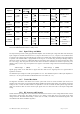
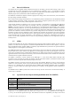
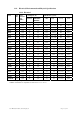
Model
Agilent #
Bandwidth
into 50 Ω
Bandwidth/
Capacitance
into 1 MΩ
Minimum
Rise Time
BW Limiter
selections
Maximum
Offset
Other
particularities
DC241A
U1064A
950 MHz
( 1 GHz
typical)
300 MHz
typical
14 pF
0.35 ns
(50Ω)
(1.2 ns
typical
1 MΩ)
20, 200, 700 MHz
(see remark below)
5 V (50Ω)
20 V (> 0.5 V
FS & 1MΩ)
200 V
(> 5V
FS & 1MΩ)
DC271 FAMILY
Max FS = 50 V
(1 MΩ)
DC265
U1063A
150 MHz 150 MHz
11 pF
2.3 ns NA 20 V BW
50
= 90 MHz
DC270
U1063A
250 MHz 250 MHz
11 pF
1.4 ns NA 20 V BW
50
= 90 MHz
DC271
U1064A
1 GHz NA 0.35 ns 20, 200, 700 MHz 5 V DC271 FAMILY
DC271A
U1064A
DC271AR
950 MHz
( 1 GHz
typical)
300 MHz
typical
14 pF
0.35 ns
(50Ω)
(1.2 ns
typical
1 MΩ)
20, 200, 700 MHz
(see remark below)
5 V (50Ω)
20 V (> 0.5 V
FS & 1MΩ)
200 V
(> 5V
FS & 1MΩ)
DC271 FAMILY
Max FS = 50 V
(1 MΩ)
The AR has only 2
channels
For 1 MΩ coupling in the DC2x1A/AR the 700 MHz Bandwidth Limiter cannot be used. Furthermore, for FS gain >
5V the 200 MHz Bandwidth Limiter is always active.
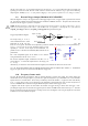
3.2.6. Input Voltage and Offset
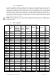
The input channel provides a fully programmable amplifier with variable input voltage and offset. Full Scale (FS)
input voltages are selectable from 50 mV to 5 V (except as shown above) in a 1, 2, 5 sequence. Care should be taken
to select an input voltage range that will allow the signal to be recorded using as much dynamic range of the digitizer
as possible. The Variable Offset is programmable in the range of ±2 V when using an FS Input Voltage setting of
500 mV or below, increasing to ± Maximum Offset for FS settings above 500 mV. The raw 8-bit ADC data values
are in the range [-128,+127] with the first and last values reserved for underflow and overflow respectively. The
midpoint value, 0, of the range corresponds to the negative of the offset voltage. Thus the Full Scale Range (FSR)
goes from
–Offset Voltage – (FS/2) to –Offset Voltage + (FS/2)
Signals going outside of the FSR will be clipped and data values for the clipped portion of a signal should be
regarded as erroneous.
The maximum input voltage for 50 Ω input impedance is ±5 V. The maximum input for 1 MΩ input impedance is
±100 V (dc + ac) except for the DC2x1A/AR models where it is ±300 V (dc + ac).
3.2.7. Vertical Resolution
The digitizers described in this manual use an ADC system with 8 bits of vertical resolution (256 levels). The
dynamic range of the ADC covers the Full Scale Range (FSR) of the Input Voltage setting. For example, if the Input
Voltage is set to 1 V then the ADC resolution is equivalent to 3.91 mV. To obtain the best dynamic range from the
ADC care should be taken to ensure that the input signal varies over more than 50% of the Input Voltage FSR
setting.
3.2.8. DC Accuracy and Linearity
The DP and DC Series digitizers use low noise front-end electronics in order to ensure voltage measurement is made
with accuracy and precision. DC voltage accuracy, at 0 V offset, is better than ±2% (±1% typical) of the input
voltage full scale. The differential linearity is better than ±0.7 LSB ( ±0.8 LSB for DC135/DC140 digitizers and
±0.9 LSB for other DC271-FAMILY digitizers).