DSOX4USBSQ USB 2.
Notices © Agilent Technologies, Inc. 2003-2013 Manual Part Number No part of this manual may be reproduced in any form or by any means (including electronic storage and retrieval or translation into a foreign language) without prior agreement and written consent from Agilent Technologies, Inc. as governed by United States and international copyright laws. Version 03.10.0000 Trademarks Microsoft®, MS-DOS®, Windows®, Windows 2000®, and Windows XP® are U.S. registered trademarks of Microsoft Corporation.
USB 2.0 Signal Analysis—At a Glance The DSOX4USBSQ USB 2.0 Signal Quality Analysis application for the InfiniiVision 4000 X- Series oscilloscopes supports two use models: • You can quickly test USB signal quality in- circuit with real- world packets. In this case: • You can use test fixtures as an easy way to probe signals. • The USBSQ analysis application's Auto Setups may need to be adjusted before analyzing real- world packets. • You can verify signal quality to USB 2.0 compliance specifications.
DSOX4USBSQ USB 2.
Contents USB 2.
Host Full Speed Signal Quality Test 46 Host Full Speed Connection 48 Host Low Speed Signal Quality Test 50 Host Low Speed Connection 52 4 Hub Upstream Signal Quality Testing Hub Upstream Hi-Speed Signal Quality Test 54 Hub Upstream Hi-Speed Connection - Differential Probe Hub Upstream Hi-Speed Connection - SMA Cables 58 Hub Upstream Hi-Speed Compliance Test Packets 59 Hub Upstream Full Speed Signal Quality Test 60 Hub Upstream Full Speed Connection 62 Hub Upstream Full Speed Compliance Test Packets 57 63
DSOX4USBSQ USB 2.0 Signal Quality Analysis Application Electrical Testing Notes 1 Preparing for Signal Quality Analysis Oscilloscope Requirements 8 Fixtures for Signal Quality Tests 9 Probe Requirements 12 Miscellaneous Cables and Devices 15 This chapter describes the equipment and software required for performing signal quality analysis with the 4000 X- Series oscilloscope and the DSOX4USBSQ USB 2.0 Signal Quality Analysis application.
1 Preparing for Signal Quality Analysis Oscilloscope Requirements The DSOX4USBSQ USB 2.0 Signal Quality Analysis application requires an Agilent InfiniiVision 4000 X- Series oscilloscope, firmware version 3.10 or later. For Hi-Speed Tests For Full and Low Speed Tests Hi- Speed tests require a 1.5 GHz bandwidth model oscilloscope. Hi- Speed tests on a 2- channel oscilloscope with single- ended SMA cable connections is not supported because the sample rate will not meet the 5 GSa/s rate that is required.
Preparing for Signal Quality Analysis 1 Fixtures for Signal Quality Tests Two different fixtures are used for Hi- Speed tests; one is for devices and other is for hosts. See “Fixtures for Hi- Speed Signal Quality Tests" on page 9. One fixture is used for Full and Low Speed tests. See “Fixture for Full/Low Speed Signal Quality Tests" on page 10.
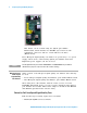
1 Preparing for Signal Quality Analysis This fixture can be ordered using the Agilent part number E2649- 60002, which includes two RF SMA (m) vertical 50- ohm termination connectors and two 4 inch USB A- to- B cables (E2646- 61601). These Hi- Speed Signal Quality test fixtures are powered by a 5 V power supply, which can be ordered using Agilent part number 0950- 2546. Equivalent power supplies can also be used.
Preparing for Signal Quality Analysis 1 This fixture can be ordered using the model number E2646A/B. DSOX4USBSQ USB 2.
1 Preparing for Signal Quality Analysis Probe Requirements Hi- Speed tests require a differential probe (see “Differential Probe Connection for Hi- Speed Signal Quality Tests" on page 12) or two single- ended SMA cable connections (see “Single- Ended SMA Cable Connection for Hi- Speed Signal Quality Tests" on page 13). Low and Full Speed host tests require single- ended probes (see “Single- Ended Probe Connection for Full/Low Speed Signal Quality Tests" on page 14).
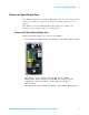
Preparing for Signal Quality Analysis Figure 1 NOTE 1 Differential Probe Setup In certain test situations, there may not be a ground connection between the oscilloscope and the device under test (DUT). This may lead to the signal seen by the differential probe to be modulated up and down due to the mid-frequency switching power supply. Connecting the oscilloscope ground to the DUT ground will be required to establish a common ground reference.
1 Preparing for Signal Quality Analysis Single-Ended Probe Connection for Full/Low Speed Signal Quality Tests Low and Full Speed host tests require two single- ended probes. Low and Full Speed device tests require three single- ended probes — the third probe is for the adjacent D- /D+ signal. The passive probes that are included with the oscilloscope are sufficient. 14 DSOX4USBSQ USB 2.
Preparing for Signal Quality Analysis 1 Miscellaneous Cables and Devices The following table lists miscellaneous cables and devices required for certain tests. Table 1 Miscellaneous Cables and Devices Equipment Required Tests and Quantities Host Hi-Speed Hub Hi-Speed Device Hi-Speed Low/Full Speed 5 m USB cable (any listed on USB-IF web site). 1 1 1 as needed 1.5 m USB cable (any listed on USB-IF web site). 1 1 n/a n/a 1 m USB cable (any listed on USB-IF web site).
1 Preparing for Signal Quality Analysis Additional Equipment and Set Up for Signal Quality Compliance Testing When performing USB 2.0 signal quality compliance testing (instead of testing the signal quality of real- world packets): • You need a high- speed electrical test bed computer and the High- Speed Electrical Test Tool Kit software (USBHSET) in order to generate compliance test packets. See “High- Speed Electrical Test Bed Computer" on page 16.
1 Preparing for Signal Quality Analysis vendor). Therefore, an automatic driver stack switching function has been implemented into the Hi- speed Electrical Test Tool for easy switching between the proprietary EHCI driver stack and that from Microsoft. Upon invocation of the HS Electrical Test Tool software, the driver stack will automatically switch to the Intel proprietary EHCI driver stack.
1 18 Preparing for Signal Quality Analysis DSOX4USBSQ USB 2.
DSOX4USBSQ USB 2.
2 Device Signal Quality Testing Device Hi-Speed Signal Quality Test Table 3 Equipment Used in Device Hi-Speed Signal Quality Tests Quantity Item Description/Model 1 Oscilloscope Agilent 4000 X-Series 1.
2 Device Signal Quality Testing 7 Press the Signals softkey. In the USB Signal Quality Signals Menu: a Press the Test Connection softkey and select whether you are using a Single-ended (with SMA cables) or Differential probe connection. b If you are using a differential connection, press the Source softkey and select the analog input source channel connected to the differential probe.
2 Device Signal Quality Testing 9 Press the Run Test softkey to run the selected signal quality test. When tests are run, the oscilloscope stops acquisitions if they are running, analyzes the data on screen, and then displays the results. NOTE Tests can take several minutes to run and cannot be cancelled once started. When the test completes, the results are automatically displayed. You can press the Display Results softkey to disable or reenable the test results display. 22 DSOX4USBSQ USB 2.
Device Signal Quality Testing DSOX4USBSQ USB 2.
2 Device Signal Quality Testing The analyzed acquisition remains on screen and can be viewed by moving or dismissing the results dialog box. You can run tests when the oscilloscope is already stopped. This is useful in the case of embedded hosts (and other cases) where the device under test (DUT) may not easily be placed in a test mode, and you want to analyze already acquired data.
Device Signal Quality Testing 2 5 Attach the differential probe to D+/D- of TP2 on the test fixture. Ensure the + polarity on the probe lines up with D+. 6 Please terminate the fixture's SMA connectors with 50 Ohm terminators. 2 1 3 4 113xA differential probe Device Under Test D+ TP2 Hi-Speed Host D- 4“ Test Port 5m Cable Init.
2 Device Signal Quality Testing 2 1 3 4 SMA cables Device Under Test D+ Hi-Speed Host 4“ TP2 D- Test Port 5m Cable Init. Port 5V Device Hi-Speed Signal Quality Test Fixture Device Hi-Speed Compliance Test Packets To set up the Host computer to transmit compliance test packets, perform these steps: 1 Invoke the HS Electrical Test Tool software on the Hi- Speed Electrical Test Bed computer. 2 Select Device and click the TEST button to open the Device Test dialog box.
Device Signal Quality Testing 2 4 Select TEST_PACKET from the Device Command drop down menu, and click EXECUTE. This forces the device under test to continuously transmit test packets. DSOX4USBSQ USB 2.
2 Device Signal Quality Testing Device Full Speed Signal Quality Test Table 4 Equipment Used in Upstream Full Speed Signal Quality Test Quantity Item Description/Model 1 Oscilloscope Agilent 4000 X-Series 3 Passive probes Probes included with the oscilloscope are sufficient. 1 Host test bed computer Any computer with the Windows XP, Windows 7, or Windows 8 operating system and hi-speed USB ports.
2 Device Signal Quality Testing When full speed tests are run on a 2- channel oscilloscope, a statement about the analysis data being under- sampled will be included in the test results. c Press the Adj D+ Source softkey and select the analog input source channel connected to the adjacent D+ signal (channel 1 in the previous connection instructions). 7 Press the Auto Setup softkey to automatically set up the oscilloscope for the selected test.
2 Device Signal Quality Testing When the test completes, the results are automatically displayed. You can press the Display Results softkey to disable or reenable the test results display. The analyzed acquisition remains on screen and can be viewed by moving or dismissing the results dialog box. You can run tests when the oscilloscope is already stopped.
2 Device Signal Quality Testing Host 5m Cable (Self-powered) Hub 1 Hi-Speed Hub 5m Cable (Self-powered) Hub 2 Full Speed Hub 5m Cable (Self-powered) Hub 3 5m Cable (Self-powered) Hub 4 5m Cable 1 2 3 (Self-powered) Hub 5 4 Probe D+ in Adjacent Device Path D- D+ D+ SQiDD Probe D- and D+ in Device Under Test Path 5m Cable Full-Speed Device Under Test Adjacent Full-Speed Device Device Full Speed Compliance Test Packets To set up the Host computer to transmit compliance test packets, perfo
2 Device Signal Quality Testing 3 In the Device Test dialog box, click Enumerate Bus once. All devices attached to the host controller should appear in the device enumeration list. If you do not know which VID/PID belongs to the device under test, detach the device under test and enumerate the bus once. Then reattach the device under test and enumerate again, this time paying attention to the new device attached.
2 Device Signal Quality Testing Device Low Speed Signal Quality Test Table 5 Equipment Used in Upstream Low Speed Signal Quality Test Quantity Item Description/Model 1 Oscilloscope Agilent 4000 X-Series 3 Passive probes Probes included with the oscilloscope are sufficient. 1 Host test bed computer Any computer with the Windows XP, Windows 7, or Windows 8 operating system and hi-speed USB ports.
2 Device Signal Quality Testing On 4- channel oscilloscopes, you are forced to use different channel pairs for the D+ and D- signals. This provides the maximum sample rate. (Channels 1 and 2 are one pair and channels 3 and 4 are the other pair.) c Press the Adj D- Source softkey and select the analog input source channel connected to the adjacent D- signal (channel 1 in the previous connection instructions). 7 Press the Auto Setup softkey to automatically set up the oscilloscope for the selected test.
2 Device Signal Quality Testing When the test completes, the results are automatically displayed. You can press the Display Results softkey to disable or reenable the test results display. The analyzed acquisition remains on screen and can be viewed by moving or dismissing the results dialog box. You can run tests when the oscilloscope is already stopped.
2 Device Signal Quality Testing Host 5m Cable (Self-powered) Hub 1 Hi-Speed Hub 5m Cable (Self-powered) Hub 2 Full Speed Hub 5m Cable (Self-powered) Hub 3 5m Cable (Self-powered) Hub 4 5m Cable 1 2 3 (Self-powered) Hub 5 4 Probe D- in Adjacent Device Path D- D+ DSQiDD Probe D- and D+ in Device Under Test Path 5m Cable Low-Speed Device Under Test Adjacent Low-Speed Device Device Low Speed Compliance Test Packets To set up the Host computer to transmit compliance test packets, perform the
Device Signal Quality Testing 2 3 In the Device Test dialog box, click Enumerate Bus once. All devices attached to the host controller should appear in the device enumeration list. If you do not know which VID/PID belongs to the device under test, detach the device under test and enumerate the bus once. Then reattach the device under test and enumerate again, this time paying attention to the new device attached.
2 38 Device Signal Quality Testing DSOX4USBSQ USB 2.
DSOX4USBSQ USB 2.
3 Host Signal Quality Testing Host Hi-Speed Signal Quality Test Table 6 Equipment Used in Host Hi-Speed Signal Quality Tests Quantity Item Description/Model 1 Oscilloscope Agilent 4000 X-Series 1.5 GHz bandwidth model 1 Oscilloscope probing solution: • Differential probe Agilent 113xA with E2678A or E2669A • SMA cables Agilent 15443A matched cable pair or equivalent 1 Host test bed computer Any computer with the Windows XP, Windows 7, or Windows 8 operating system and hi-speed USB ports.
3 Host Signal Quality Testing If you are using a single- ended (SMA cables) connection, press the DP SMA softkey and select the analog input source channel connected to the D+ signal. Then, press the DN SMA softkey and select the analog input source channel connected to the D- signal. On 4- channel oscilloscopes, you are forced to use different channel pairs for the D+ and D- signals. This provides the maximum sample rate. (Channels 1 and 2 are one pair and channels 3 and 4 are the other pair.
3 Host Signal Quality Testing 8 Press the Run Test softkey to run the selected signal quality test. When tests are run, the oscilloscope stops acquisitions if they are running, analyzes the data on screen, and then displays the results. NOTE Tests can take several minutes to run and cannot be cancelled once started. When the test completes, the results are automatically displayed. You can press the Display Results softkey to disable or reenable the test results display.
3 Host Signal Quality Testing Host Hi-Speed Connection - Differential Probe Perform these connection steps: 1 Attach the 5V power supply to J5 of the E2649- 66402 Host Hi- Speed Signal Quality test fixture and verify the green POWER LED is lit. a Set the TEST switch (S1) of the test fixture to the ON position and verify the yellow TEST LED is lit. 2 Attach the Agilent 113xA differential probe to TP2 of the test fixture.
3 Host Signal Quality Testing Host Hi-Speed Connection - SMA Cables 1 Attach the 5V power supply to J5 of the E2649- 66402 Hi- Speed signal quality test fixture. Verify the green POWER LED is lit. 2 Set the TEST switch (S1) of the test fixture to the ON position and verify that the yellow TEST LED is lit. 3 Attach the SMA cables to SMA connectors D+ and D- on the test fixture. 1 2 3 4 SMA cables Host Under Test D+ 4“ TP2 D- Host Hi-Speed Signal Quality Test Fixture Test Port Init.
Host Signal Quality Testing 3 3 In the Host Test dialog box, select TEST_PACKET from the Port Control drop down menu. 4 Enter the port number of the port under test. 5 Click EXECUTE. This forces the port under test to continuously transmit test packets. DSOX4USBSQ USB 2.
3 Host Signal Quality Testing Host Full Speed Signal Quality Test Table 7 Equipment Used in Host Downstream Full Speed Signal Quality Test Quantity Item Description/Model 1 Oscilloscope Agilent 4000 X-Series 2 Passive probes Probes included with the oscilloscope are sufficient. 1 Host test bed computer Any computer with the Windows XP, Windows 7, or Windows 8 operating system and hi-speed USB ports.
3 Host Signal Quality Testing When full speed tests are run on a 2- channel oscilloscope, a statement about the analysis data being under- sampled will be included in the test results. 7 Press the Auto Setup softkey to automatically set up the oscilloscope for the selected test. For optimal test results, you can make adjustments to the auto setup. Generally, you want one packet of data, plus the time of one bit on each end, across the oscilloscope's display.
3 Host Signal Quality Testing The analyzed acquisition remains on screen and can be viewed by moving or dismissing the results dialog box. You can run tests when the oscilloscope is already stopped. This is useful in the case of embedded hosts (and other cases) where the device under test (DUT) may not easily be placed in a test mode, and you want to analyze already acquired data.
Host Signal Quality Testing 2 1 3 3 4 Probe D+ and D- in Host Under Test Path (Self-powered) Hub 1 Full Speed Hub (Self-powered) Hub 2 SQiDD D+ 5m Cable D- Hi-Speed Hub Host Under Test 5m Cable Root Hub (Self-powered) Hub 3 5m Cable (Self-powered) Hub 4 5m Cable 5m Cable (Self-powered) Hub 5 Full Speed Test Device 5m Cable DSOX4USBSQ USB 2.
3 Host Signal Quality Testing Host Low Speed Signal Quality Test Table 8 Equipment Used in Host Downstream Low Speed Signal Quality Test Quantity Item Description/Model 1 Oscilloscope Agilent 4000 X-Series 2 Passive probes Probes included with the oscilloscope are sufficient. 1 Host test bed computer Any computer with the Windows XP, Windows 7, or Windows 8 operating system and hi-speed USB ports.
3 Host Signal Quality Testing For optimal test results, you can make adjustments to the auto setup. Generally, you want one packet of data, plus the time of one bit on each end, across the oscilloscope's display. Also, vertical scale and offset should be adjusted so that the signals take six vertical divisions without being clipped. You should see the transmitted test packet on the oscilloscope as below. 8 Press the Run Test softkey to run the selected signal quality test.
3 Host Signal Quality Testing See Also • Chapter 6, “Saving Test Results to an HTML File,” starting on page 81 Host Low Speed Connection Perform these connection steps: 1 Use the passive probes included with the oscilloscope. 2 Attach the passive probes to the oscilloscope's Channel 3 and Channel 2 inputs. 3 Attach the SQiDD board to the root hub on the host under test. 4 Attach a low speed device to the same section of the SQiDD board. If the section has a switch, it should be set to ON.
DSOX4USBSQ USB 2.
4 Hub Upstream Signal Quality Testing Hub Upstream Hi-Speed Signal Quality Test Table 9 Equipment Used in Hub Hi-Speed Signal Quality Test - Upstream Facing Ports Quantity Item Description/Model 1 Oscilloscope Agilent 4000 X-Series 1.
4 Hub Upstream Signal Quality Testing 7 Press the Signals softkey. In the USB Signal Quality Signals Menu: a Press the Test Connection softkey and select whether you are using a Single-ended (with SMA cables) or Differential probe connection. b If you are using a differential connection, press the Source softkey and select the analog input source channel connected to the differential probe.
4 Hub Upstream Signal Quality Testing 9 Press the Run Test softkey to run the selected signal quality test. When tests are run, the oscilloscope stops acquisitions if they are running, analyzes the data on screen, and then displays the results. NOTE Tests can take several minutes to run and cannot be cancelled once started. When the test completes, the results are automatically displayed. You can press the Display Results softkey to disable or reenable the test results display.
4 Hub Upstream Signal Quality Testing Hub Upstream Hi-Speed Connection - Differential Probe Perform these connection steps: 1 Attach the 5V power supply to J5 of the E2649- 66401 Device Hi- Speed Signal Quality test fixture. Leave the TEST switch at the OFF position. Verify green POWER LED is lit, and yellow TEST LED is off. 2 Connect the [TEST PORT] of the test fixture into the upstream facing port of the hub under test, using the 4" USB cable.
4 Hub Upstream Signal Quality Testing Hub Upstream Hi-Speed Connection - SMA Cables 1 Attach the 5V power supply to J5 of the E2649- 66401 Device Hi- Speed signal quality test fixture. Leave the TEST switch at the OFF position. Verify the green POWER LED is lit and the yellow TEST LED is not lit. 2 Connect the [TEST PORT] of the Device Hi- speed Signal Quality test fixture into the upstream facing port of the device under test, using the 4" USB cable.
4 Hub Upstream Signal Quality Testing Hub Upstream Hi-Speed Compliance Test Packets To set up the Host computer to transmit compliance test packets, perform these steps: 1 Invoke the HS Electrical Test Tool software on the Hi- Speed Electrical Test Bed computer. Select Hub and click the TEST button to enter the Hub Test dialog box. 2 In the Hub Test dialog box, the hub under test should be enumerated with the hub's VID shown together with the USB address.
4 Hub Upstream Signal Quality Testing Hub Upstream Full Speed Signal Quality Test Table 10 Equipment Used in Upstream Full Speed Signal Quality Test Quantity Item Description/Model 1 Oscilloscope Agilent 4000 X-Series 3 Passive probes Probes included with the oscilloscope are sufficient. 1 Host test bed computer Any computer with the Windows XP, Windows 7, or Windows 8 operating system and hi-speed USB ports.
4 Hub Upstream Signal Quality Testing When full speed tests are run on a 2- channel oscilloscope, a statement about the analysis data being under- sampled will be included in the test results. c Press the Adj D+ Source softkey and select the analog input source channel connected to the adjacent D+ signal 7 Press the Auto Setup softkey to automatically set up the oscilloscope for the selected test. For optimal test results, you can make adjustments to the auto setup.
4 Hub Upstream Signal Quality Testing When the test completes, the results are automatically displayed. You can press the Display Results softkey to disable or reenable the test results display. The analyzed acquisition remains on screen and can be viewed by moving or dismissing the results dialog box. You can run tests when the oscilloscope is already stopped.
4 Hub Upstream Signal Quality Testing Host 5m Cable (Self-powered) Hub 1 Hi-Speed Hub 5m Cable (Self-powered) Hub 2 Full Speed Hub 5m Cable (Self-powered) Hub 3 5m Cable (Self-powered) Hub 4 5m Cable 1 2 3 (Self-powered) Hub 5 4 Probe D+ in Adjacent Device Path D- D+ D+ SQiDD Probe D- and D+ in Device Under Test Path upstream port Hub Under Test 5m Cable Adjacent Full-Speed Device Hub Upstream Full Speed Compliance Test Packets To set up the Host computer to transmit compliance test p
4 Hub Upstream Signal Quality Testing 3 In the Device Test dialog box, click Enumerate Bus once. All devices attached to the host controller should appear in the device enumeration list. If you do not know which VID/PID belongs to the device under test, detach the device under test and enumerate the bus once. Then reattach the device under test and enumerate again, this time paying attention to the new device attached.
DSOX4USBSQ USB 2.
5 Hub Downstream Signal Quality Testing Hub Downstream Hi-Speed Signal Quality Test Table 11 Equipment Used in Hub Hi-Speed Signal Quality Test - Downstream Facing Ports Quantity Item Description/Model 1 Oscilloscope Agilent 4000 X-Series 1.
5 Hub Downstream Signal Quality Testing If you are using a single- ended (SMA cables) connection, press the DP SMA softkey and select the analog input source channel connected to the D+ signal. Then, press the DN SMA softkey and select the analog input source channel connected to the D- signal. On 4- channel oscilloscopes, you are forced to use different channel pairs for the D+ and D- signals. This provides the maximum sample rate. (Channels 1 and 2 are one pair and channels 3 and 4 are the other pair.
5 Hub Downstream Signal Quality Testing 8 Press the Run Test softkey to run the selected signal quality test. When tests are run, the oscilloscope stops acquisitions if they are running, analyzes the data on screen, and then displays the results. NOTE Tests can take several minutes to run and cannot be cancelled once started. When the test completes, the results are automatically displayed. You can press the Display Results softkey to disable or reenable the test results display.
Hub Downstream Signal Quality Testing 5 Hub Downstream Hi-Speed Connection - Differential Probe Perform these connection steps: 1 Attach the 5V power supply to J5 of the E2649- 66402 Host Hi- Speed Signal Quality test fixture. Set the Test switch to the TEST position. Verify green POWER LED and yellow TEST LED are both lit. 2 Attach the Agilent 113xA differential probe to TP2 of the test fixture. Ensure the + polarity on the probe lines up with D+ on the fixture, located nearest to the USB connector.
5 Hub Downstream Signal Quality Testing Hub Downstream Hi-Speed Connection - SMA Cables Perform these connection steps: 1 Attach the 5V power supply to J5 of the E2649- 66402 Host Hi- Speed Signal Quality test fixture. Set the TEST switch to the ON position. Verify green POWER LED and yellow TEST LED are both lit. 2 Connect the upstream port of the hub to a high- speed root port of the test bed computer.
5 Hub Downstream Signal Quality Testing Hub Downstream Hi-Speed Compliance Test Packets To set up the Host computer to transmit compliance test packets, perform these steps: 1 Invoke the HS Electrical Test Tool software on the Hi- Speed Electrical Test Bed computer. Select Hub and click the TEST button to enter the Hub Test dialog box. 2 In the Hub Test dialog box, click the Enumerate Bus button once. The hub under test should be enumerated with the hub's VID shown together with the USB address.
5 Hub Downstream Signal Quality Testing Hub Downstream Full Speed Signal Quality Test Table 12 Equipment Used in Hub Downstream Full Speed Signal Quality Test Quantity Item Description/Model 1 Oscilloscope Agilent 4000 X-Series 2 Passive probes Probes included with the oscilloscope are sufficient. 1 Host test bed computer Any computer with the Windows XP, Windows 7, or Windows 8 operating system and hi-speed USB ports.
5 Hub Downstream Signal Quality Testing When full speed tests are run on a 2- channel oscilloscope, a statement about the analysis data being under- sampled will be included in the test results. 7 Press the Auto Setup softkey to automatically set up the oscilloscope for the selected test. For optimal test results, you can make adjustments to the auto setup. Generally, you want one packet of data, plus the time of one bit on each end, across the oscilloscope's display.
5 Hub Downstream Signal Quality Testing The analyzed acquisition remains on screen and can be viewed by moving or dismissing the results dialog box. You can run tests when the oscilloscope is already stopped. This is useful in the case of embedded hosts (and other cases) where the device under test (DUT) may not easily be placed in a test mode, and you want to analyze already acquired data.
5 Hub Downstream Signal Quality Testing Host 1 2 3 4 Probe D+ and D- in Host Under Test Path 5m Cable Full Speed Test Device (Self-powered) Hub 1 Full Speed Hub 5m Cable (Self-powered) Hub 2 SQiDD D+ Hi-Speed Hub 5m Cable D- (Self-powered) Hub 3 5m Cable (Self-powered) Hub 4 5m Cable Hub Under Test 5m Cable DSOX4USBSQ USB 2.
5 Hub Downstream Signal Quality Testing Hub Downstream Low Speed Signal Quality Test Table 13 Equipment Used in Hub Downstream Low Speed Signal Quality Test Quantity Item Description/Model 1 Oscilloscope Agilent 4000 X-Series 2 Passive probes Probes included with the oscilloscope are sufficient. 1 Host test bed computer Any computer with the Windows XP, Windows 7, or Windows 8 operating system and hi-speed USB ports.
5 Hub Downstream Signal Quality Testing 7 Press the Auto Setup softkey to automatically set up the oscilloscope for the selected test. For optimal test results, you can make adjustments to the auto setup. Generally, you want one packet of data, plus the time of one bit on each end, across the oscilloscope's display. Also, vertical scale and offset should be adjusted so that the signals take six vertical divisions without being clipped.
5 Hub Downstream Signal Quality Testing You can run tests when the oscilloscope is already stopped. This is useful in the case of embedded hosts (and other cases) where the device under test (DUT) may not easily be placed in a test mode, and you want to analyze already acquired data. See Also • Chapter 6, “Saving Test Results to an HTML File,” starting on page 81 Hub Downstream Low Speed Connection Perform these connection steps: 1 Use the passive probes included with the oscilloscope.
5 Hub Downstream Signal Quality Testing Host 1 2 3 4 Probe D+ and D- in Host Under Test Path SQiDD 5m Cable (Self-powered) Hub 1 D- D+ Full Speed Hub 5m Cable (Self-powered) Hub 2 Low Speed Test Device (Mouse) 5m Cable (Self-powered) Hub 3 5m Cable 5m Cable (Self-powered) Hub 4 Hub Under Test DSOX4USBSQ USB 2.
5 80 Hub Downstream Signal Quality Testing DSOX4USBSQ USB 2.
DSOX4USBSQ USB 2.0 Signal Quality Analysis Application Electrical Testing Notes 6 Saving Test Results to an HTML File To save USB 2.0 signal quality test results: 1 Connect a USB storage device to one of the oscilloscope's USB Host ports. 2 On the oscilloscope's front panel, press [Save/Recall] > Save > Format and select the USB Signal Quality option. 3 Press the second softkey; then, use the File Explorer to browse to the location where you want to save the test results file.
6 82 Saving Test Results to an HTML File DSOX4USBSQ USB 2.
DSOX4USBSQ USB 2.0 Signal Quality Analysis Application Electrical Testing Notes A Probing Hi-Speed Signals with InfiniiMode Using SQiDD as a Feedthrough If you need a feed- through that will let you probe Hi- Speed signals with the N2750A Series InfiniiMode probe, you can use the E2646A/B SQiDD test fixture (normally used for Full and Low Speed testing) and InfiniiMode probes. Use the center section of the board as the feed- though. Probe the signals using the test points.
A 84 Probing Hi-Speed Signals with InfiniiMode Using SQiDD as a Feedthrough DSOX4USBSQ USB 2.
Index Numerics 01131-68703 header adapter, 10 4000 X-Series oscilloscopes, 8 connection, hub upstream hi-speed, differential probe, 57 connection, hub upstream hi-speed, SMA cables, 58 A D at a glance, 3 decode and triggering, USB2.0, 8 device full speed signal quality test, 28 device hi-speed signal quality test, 20 device low speed signal quality test, 33 device signal quality testing, 19 devices, USB, 15 differential probe connection, 12 DSOX4USBFL USB 2.
Index USB electrical test fixtures, 9 USBHSET software, 16 86 DSOX4USBSQ USB 2.