
Technical data

24 DSOX4USBSQ USB 2.0 Signal Quality Analysis Application Electrical Testing Notes
2 Device Signal Quality Testing
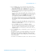
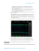
The analyzed acquisition remains on screen and can be viewed by
moving or dismissing the results dialog box.
You can run tests when the oscilloscope is already stopped. This is
useful in the case of embedded hosts (and other cases) where the
device under test (DUT) may not easily be placed in a test mode, and
you want to analyze already acquired data.
See Also • Chapter 6, “Saving Test Results to an HTML File,” starting on page 81
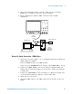
Device Hi-Speed Connection - Differential Probe
Perform these connection steps:
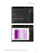
1 Attach the 5V power supply to J5 of the E2649- 66401 Device Hi- Speed
signal quality test fixture.
Leave the TEST switch at the OFF position.
Verify the green POWER LED is lit and the yellow TEST LED is not lit.
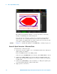
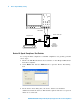
2 Connect the [TEST PORT] of the Device Hi-speed Signal Quality test
fixture into the upstream facing port of the device under test, using the
4" USB cable.
3 Connect the [INIT PORT] of the test fixture to a Hi- speed capable port
of the Test Bed Computer, using a USB cable.
4 Apply power to the device.