
Technical data

Device Signal Quality Testing 2
DSOX4USBSQ USB 2.0 Signal Quality Analysis Application Electrical Testing Notes 25
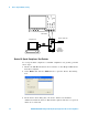
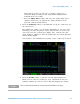
5 Attach the differential probe to D+/D- of TP2 on the test fixture.
Ensure the + polarity on the probe lines up with D+.
6 Please terminate the fixture's SMA connectors with 50 Ohm
terminators.
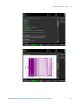
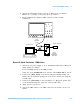
Device Hi-Speed Connection - SMA Cables
1 Attach the 5V power supply to J5 of the E2649- 66401 Device Hi- Speed
signal quality test fixture.
Leave the TEST switch at the OFF position.
Verify the green POWER LED is lit and the yellow TEST LED is not lit.
2 Connect the [TEST PORT] of the Device Hi-speed Signal Quality test
fixture into the upstream facing port of the device under test, using the
4" USB cable.
3 Connect the [INIT PORT] of the test fixture to a Hi- speed capable port
of the Test Bed Computer, using the 5 meter USB cable.
4 Apply power to the device.
5 Attach the SMA cables to the SMA connectors D+ and D- on the test
fixture.
1
2
3
4
Hi-Speed Host
5m Cable
Device Under Test
4“
Init. Port
Test
Port
5V
D+
D-
TP2
Device
Hi-Speed
Signal Quality
Test Fixture
113xA
differential
probe