
Technical data
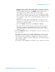

Host Signal Quality Testing 3
DSOX4USBSQ USB 2.0 Signal Quality Analysis Application Electrical Testing Notes 43
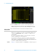
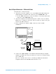
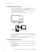
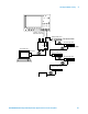
Host Hi-Speed Connection - Differential Probe
Perform these connection steps:
1 Attach the 5V power supply to J5 of the E2649- 66402 Host Hi- Speed
Signal Quality test fixture and verify the green POWER LED is lit.
a Set the TEST switch (S1) of the test fixture to the ON position and
verify the yellow TEST LED is lit.
2 Attach the Agilent 113xA differential probe to TP2 of the test fixture.
Ensure the + polarity on the probe lines up with D+, which is the pin
nearest the USB connector.
3 Please terminate the fixture's SMA connectors with 50 Ohm
terminators.
4 Connect the [TEST PORT] of the E2649- 66402 Host Hi- Speed Signal
Quality test fixture into the port under test of the host controller, using
the 4" USB cable.
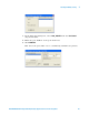
The host controller here refers to the Hi- speed Electrical Test Bed
Computer that has the HS Electrical Test Tool on it.
1
2
34
Host Under Test
Init. Port
Test
Port
5V
D+
D-
TP2
Host Hi-Speed
Signal Quality
Test Fixture
4“
113xA
differential
probe