
Technical data

54 DSOX4USBSQ USB 2.0 Signal Quality Analysis Application Electrical Testing Notes
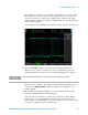
4 Hub Upstream Signal Quality Testing
Hub Upstream Hi-Speed Signal Quality Test
To set up and run the Hub upstream Hi- Speed signal quality tests:
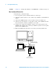
1 Connect the USB Device, test fixtures, and equipment:
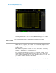
• If you are probing the test fixture using a differential probe, see
"Hub Upstream Hi- Speed Connection - Differential Probe" on
page 57.
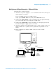
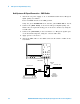
• If you are probing the test fixture using SMA cables, see "Hub
Upstream Hi- Speed Connection - SMA Cables" on page 58.
2 Set up the test signal/packet that will be analyzed.
To set up the test packets used for compliance testing, see "Hub
Upstream Hi- Speed Compliance Test Packets" on page 59.
3 On the Device Hi- Speed Signal Quality test fixture, place the TEST
switch (S1) in the ON position.
Verify the yellow TEST LED is lit.
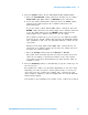
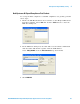
4 On the oscilloscope's front panel, press the [Analyze] key.
5 In the Analyze Menu, press the Features softkey; then, select USB Signal
Quality.
6 Press the Te st softkey and select the Device Hi-Speed Signal Quality test.
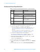
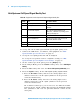
Table 9 Equipment Used in Hub Hi-Speed Signal Quality Test - Upstream Facing Ports
Quantity Item Description/Model
1 Oscilloscope Agilent 4000 X-Series 1.5 GHz bandwidth
model
1 Oscilloscope probing solution:
• Differential probe Agilent 113xA with E2678A or E2669A
• SMA cables Agilent 15443A matched cable pair or
equivalent
1 Host test bed computer Any computer with the Windows XP,
Windows 7, or Windows 8 operating system
and hi-speed USB ports.
1 Device Hi-Speed Signal Quality
test fixture and 4" USB cable
Agilent E2649-66401
1 5V power supply Agilent 0950-2546 or equivalent