
Technical data

62 DSOX4USBSQ USB 2.0 Signal Quality Analysis Application Electrical Testing Notes
4 Hub Upstream Signal Quality Testing
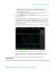
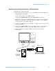
When the test completes, the results are automatically displayed. You
can press the Display Results softkey to disable or reenable the test
results display.
The analyzed acquisition remains on screen and can be viewed by
moving or dismissing the results dialog box.
You can run tests when the oscilloscope is already stopped. This is
useful in the case of embedded hosts (and other cases) where the
device under test (DUT) may not easily be placed in a test mode, and
you want to analyze already acquired data.
See Also • Chapter 6, “Saving Test Results to an HTML File,” starting on page 81
Hub Upstream Full Speed Connection
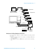
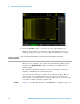
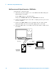
Perform these connection steps:
1 Attach the passive probes to the oscilloscope's channel Channel 2,
Channel 3 and Channel 1 inputs.
2 Attach the SQiDD board to two USB ports at the end of 5 self- powered
hubs and a host system. Hub #1 has to be a hi- speed hub and hub #2
has to be a full speed hub. The rest of the hubs can be either hi- speed
or full speed hubs.
3 Attach a full speed hub under test to the same section of the SQiDD
board. If the section has a switch, it should be set to ON.
4 Attach another full speed device to the adjacent section of the SQiDD
board. This is for triggering purposes.
5 Connect the oscilloscope Channel 2 probe to D+ probe point of the hub
under test portion. Connect the oscilloscope Channel 3 probe to the D-
probe point of the hub under test portion. Connect the oscilloscope
Channel 1 probe to the D+ probe point on the adjacent device section
of the SQiDD board.
NOTE
Placing a full speed and/or a high-speed device downstream of a full speed hub forces both
to operate in full speed mode.
NOTE
Use a full-speed hub if device under test has embedded hub function. Otherwise the
oscilloscope will falsely trigger.