
Technical data


76 DSOX4USBSQ USB 2.0 Signal Quality Analysis Application Electrical Testing Notes
5 Hub Downstream Signal Quality Testing
Hub Downstream Low Speed Signal Quality Test
To set up and run the Hub downstream Low Speed signal quality tests:
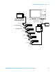
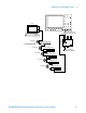
1 Connect the USB Device, test fixtures, and equipment. See "Hub
Downstream Low Speed Connection" on page 78.
2 Set up the test signal/packet that will be analyzed.
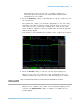
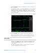
Hubs produce downstream signals that can be tested. Connect a known
good Low Speed device to the hub under test and capture a Low Speed
packet to perform the eye pattern analysis.
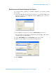
3 On the oscilloscope's front panel, press the [Analyze] key.
4 In the Analyze Menu, press the Features softkey; then, select USB Signal
Quality.
5 Press the Te st softkey and select the Host Low Speed Signal Quality test.
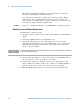
6 Press the Signals softkey. In the USB Signal Quality Signals Menu:
a Press the D+ Source softkey and select the analog input source
channel connected to the D+ signal (channel 2 in the previous
connection instructions).
b Press the D- Source softkey and select the analog input source
channel connected to the D- signal (channel 3 in the previous
connection instructions).
On 4- channel oscilloscopes, you are forced to use different channel
pairs for the D+ and D- signals. This provides the maximum sample
rate. (Channels 1 and 2 are one pair and channels 3 and 4 are the
other pair.)
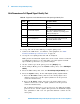
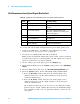
Table 13 Equipment Used in Hub Downstream Low Speed Signal Quality Test
Quantity Item Description/Model
1 Oscilloscope Agilent 4000 X-Series
2 Passive probes Probes included with the oscilloscope are
sufficient.
1 Host test bed computer Any computer with the Windows XP,
Windows 7, or Windows 8 operating system
and hi-speed USB ports.
1 SQiDD board Agilent E2646A/B
1low speed USB device Any USB mouse
5 USB self-powered hubs Any listed on USB-IF web site
5 5 meter USB cables Any listed on USB-IF web site