Agilent E1326B/E1411B 5 1/2 Digit Multimeter User’s Manual E1326-90009 Printed in USA July 2004 E0704 *E1326-90009* S1
Contents HP E1326B/E1411B 5 1/2 Digit Multimeter User’s Manual Warranty . . . . . . . . . . WARNINGS . . . . . . . . Safety Symbols . . . . . . Declaration of Conformity . Declaration of Conformity . Reader Comment Sheet . . . . . . . . . . . . . . . . . . . . . . . . . . . . . . . . . . . . . . . . . . . . . . . . . . . . . . . . . . . . . . . . . . . . . . . . . . . . . . . . . . . . . . . . . . . . . . . . . . . . . . . . . . . . . . . . . . . . . . . . . . . . . . . . . . . . . .
Making Multiple Burst Measurements . . . . . . . . . . . . . . . . . . . . . . . . . . Scanning a Channel List . . . . . . . . . . . . . . . . . . . . . . . . . . . . . . . . . . Making Multiple Scans . . . . . . . . . . . . . . . . . . . . . . . . . . . . . . . . . . Making Multiple Paced Scans . . . . . . . . . . . . . . . . . . . . . . . . . . . . . . . Making an Externally Triggered Scan . . . . . . . . . . . . . . . . . . . . . . . . . . . Scanning Switchbox Channels (E1326B/E1351A) . . . . . . . . . .
Saving Multimeter Configurations . . . . . . . . . . . . . . . . . . . . . . . . . . . . 114 How to Save and Recall a Configuration . . . . . . . . . . . . . . . . . . . . . . . 114 Chapter 5. HP E1326B/E1411B Multimeter Command Reference . . . . . . . . . . . . . 117 Using This Chapter . . . . . . . Command Types . . . . . . . . . Common Command Format SCPI Command Format . . Linking Commands . . . . . SCPI Command Reference . . . ABORt . . . . . . . . . . . . . . CALibration . . . . . . . . . . .
:VME:STATe . . . . . . . . . . . . . . . . . . . . . . . . . . . . . . . . . . . . . 152 :VME:STATe? . . . . . . . . . . . . . . . . . . . . . . . . . . . . . . . . . . . . 152 OUTPut . . . . . . . . . . . . . . . . . . . . . . . . . . . . . . . . . . . . . . . . . . 153 n :TTLTrg [:STATe] . . . . . . . . . . . . . . . . . . . . . . . . . . . . . . . . . 153 :TTLTrgn[:STATe]? . . . . . READ? . . . . . . . . . . . . . . . SAMPle . . . . . . . . . . . . . . :COUNt . . . . . . . . . . . . :COUNt? . . . . . .
:COUNt? . . . . . . . . . . . . . . . . :DELay . . . . . . . . . . . . . . . . . :DELay? . . . . . . . . . . . . . . . . . :DELay:AUTO . . . . . . . . . . . . . :DELay:AUTO? . . . . . . . . . . . . [:IMMediate] . . . . . . . . . . . . . . :SOURce . . . . . . . . . . . . . . . . :SOURce? . . . . . . . . . . . . . . . . IEEE 488.2 Common Command Reference Command Quick Reference . . . . . . . . . . . . . . . . . . . . . . . . . . . . . . . . . . . . . . . . . . . . . . . . . . . . . . . . . . . . . . .
Reading the Device Type Register . . . . Reading the Query Response Register . . Reading an Error Code . . . . . . . . . . Stand-Alone Multimeter Measurements . Scanning Multimeter Measurements . . . Useful Tables . . . . . . . . . . . . . . . . . Command and Parameter Opcodes . . . . Register-Based Programming Error Codes Multimeter Power-On Settings . . . . . . Function and Aperture Change Times . . VME Interrupts . . . . . . . . . . . . . . . . . . . . . . . . . . . . . . . . . . . . . . . . . . . . .
Certification Hewlett-Packard Company certifies that this product met its published specifications at the time of shipment from the factory. HewlettPackard further certifies that its calibration measurements are traceable to the United States National Institute of Standards and Technology (formerly National Bureau of Standards), to the extent allowed by that organization’s calibration facility, and to the calibration facilities of other International Standards Organization members.
Documentation History All Editions and Updates of this manual and their creation date are listed below. The first Edition of the manual is Edition 1. The Edition number increments by 1 whenever the manual is revised. Updates, which are issued between Editions, contain replacement pages to correct or add additional information to the current Edition of the manual. Whenever a new Edition is created, it will contain all of the Update information for the previous Edition.
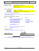
DECLARATION OF CONFORMITY SA According to ISO/IEC Guide 22 and CEN/CENELEC EN 45014 Manufacturer’s Name: Manufacturer’s Address: Agilent Technologies, Incorporated Measurement Product Generation Unit th 815 14 ST. S.W. Loveland, CO 80537 USA Declares, that the product Product Name: Model Number: Product Options: B-Size VXI 5 ½ Digital Multimeter E1326B This declaration covers all options of the above product(s).
DECLARATION OF CONFORMITY SA According to ISO/IEC Guide 22 and CEN/CENELEC EN 45014 Manufacturer’s Name: Manufacturer’s Address: Agilent Technologies, Incorporated Measurement Product Generation Unit th 815 14 ST. S.W. Loveland, CO 80537 USA Declares, that the product Product Name: Model Number: Product Options: 5 ½ Digit Multimeter E1411B This declaration covers all options of the above product(s).
Chapter 1 Getting Started with the HP E1326B/E1411B Multimeter About This Chapter This chapter introduces you the B-size HP E1326B and C-size HP E1411B 51⁄2 - Digit Multimeters. The main sections of the chapter are: • Multimeter Overview. . . . . . . . . . . . . . . . . . . . . . . . . . . . . . . Page 13 • Introduction to Operation. . . . . . . . . . . . . . . . . . . . . . . . . . . .
set the addresses in order to create an instrument. The guide should be your starting point toward using the multimeter. The functions and features of the multimeter are presented in the following functional, electrical, and physical descriptions. Functional Description The 51⁄2 - digit multimeter can be used stand-alone, or combined with multiplexers (for example, HP E1345A/46A/47A/51A/52A/55A/56A/ 57A/58A or HP E1460A/76A) to form a scanning multimeter.
Table 1-1. HP E1326B/E1411B Operating Characteristics DC Voltage Ranges Resolution Accuracy (90 days) Max Rdgs/sec 0.125V, 1.0V, 8.0V, 64.0V, 300V full scale. 120nV on 0.125V range with 20/16.7 msec aperture time. 0.01% 13,150 AC RMS Voltage Ranges Resolution Accuracy (90 days) Frequency Range 0.0875V, 0.7V, 5.6V, 44.8V, 300V full scale. 29.8nV on 0.0875V range with 320/267 msec aperture time. 0.
Introduction to Operation This section contains information on checking communication between the multimeter, mainframe, and computer. It includes information on returning the multimeter to a known operating state should programming errors occur or if you simply want to start over. It also shows how to send a command to configure the multimeter and make a measurement. Note Multimeter Self-Test The HP E1411B has a "Failed" annunciator and an "Access" annunciator on the faceplate.
Table 1-2. HP E1326/E1411 Self-Test Codes Self-Test Code Description 0 Test passed. 1 Multimeter does not respond to the self-test. 2 Invalid communication between the multimeter’s two on-board processors. 3 Data line test between the multimeter and the mainframe command module failed. 4 Invalid communication between the multimeter and mainframe command module. If self-test code 1, 2, 3, or 4 occurs, return the multimeter to Hewlett-Packard for repair.
Table 1-3. HP E1326/E1411 Power-on Settings Parameter Setting FUNCtion VOLT:DC VOLTage:RANGe 8V RESistance:RANGe 16384Ω VOLTage:RANGe:AUTO ON RESistance:RANGe:AUTO ON VOLTage:RESolution 7.629 µV RESistance:RESolution 15.6 mΩ VOLTage:APERture 16.7 ms or 20 ms (based on line frequency) RESistance:APERture 16.
Clearing the Multimeter When the multimeter is selected from the HP E1301A mainframe menu, the multimeter is cleared by pressing the “Clear Instr” key on the front panel. The multimeter is also cleared by sending the following command from an HP 9000 Series 200 or Series 300 controller: CLEAR 70903 Clearing the multimeter: – allows you to regain control without cycling power and without setting the power-on configuration.
The error queue can store up to 30 error messages which are retrieved in a first in, first out (FIFO) manner. When there are no error messages in the queue, a code of 0 and the message "No Error" are returned. Errors generated during front panel operation are displayed but are not stored in the error queue. Note Making a Measurement The HP E1326B/E1411B multimeter can be configured and make measurements using the MEASure command.
Chapter 2 Configuring the HP E1326B/E1411B Multimeter About This Chapter This chapter contains information on connecting input signals to the multimeter using multiplexers and using the terminals on the multimeter’s faceplate. The main sections of the chapter are: • • • • • WARNING Installation Overview. . . . . . . . . . . . . . . . . . . . . . . . . . . . . . . Input Characteristics . . . . . . . . . . . . . . . . . . . . . . . . . . . . . . . Connecting Input Signals. . . . . . . . . . . . . . . . .
Setting the Logical Address Switch Figure 2-1 shows the location and settings of the multimeter’s logical address switch. The switch has a factory setting of 24 which is equivalent to a secondary HP-IB address of 03. If you have more than one multimeter, you must change the logical address to some other multiple of 8 (for example, 32, 40, 48...), as there can only be one instrument per secondary address. Figure 2-1.
Forming a Scanning Multimeter If multiplexers are used to form a scanning multimeter, they must be assigned successive logical addresses beginning with the address immediately following that of the multimeter. An example is shown in Figure 2-2. The scanning multimeter can consist of relay multiplexers, FET multiplexers, or a combination of both. See “Connecting Multiplexers” on page 30 for information on physically connecting the multiplexers to the multimeter. Figure 2-2.
VXIbus Interrupt Lines The multimeter sends interrupts to, and receives acknowledgements from the slot 0 module via the VXIbus backplane interrupt lines. Since the multimeter is a nonprogrammable interrupter, the interrupt line is selected with the multimeter’s IRQ jumper. There are seven backplane interrupt lines. At the factory, the IRQ jumper is set to line 1.
HP E1326B Internal Installation When the HP E1326B is installed in an HP E1300A/E1301A/E1302A mainframe, it occupies one slot. However, the faceplate to which the input terminals are connected covers up an additional slot. This prevents another module from being installed in the slot directly above the multimeter. To make the two slots available to other modules, the HP E1326B can be installed internal to the mainframe (in slot 2) using an internal installation kit (HP P/N E1326-80004).
Installing the HP E1411B in a Mainframe The HP E1411B multimeter can be installed in any slot (except slot 0) in a C-size VXIbus mainframe. Refer to Figure 2-5 to install the E1411B in a mainframe. Set the extraction levers out. Slide the multimeter into any slot (except slot 0) until the backplane connectors touch. Seat the multimeter into the mainframe by pushing in the extraction levers. Tighten the top and bottom screws to secure the multimeter to the mainframe.
The Reference Frequency Setting the Reference Frequency In many data acquisition applications, DC voltage and resistance measurements are often made in the presence of normal mode noise. This type of noise emanates from the surrounding environment, primarily from 50 Hz and 60 Hz power lines. The HP E1326B/E1411B multimeter is able to reject normal mode noise by using an integrating analog-to-digital (A/D) converter.
Input Characteristics The multimeter is a floating, balanced differential multimeter. Floating means the multimeter’s input terminals are isolated from its chassis. A balanced differential multimeter is one where the input impedance between HI and COM is the same as the impedance between LO and COM (see Figure 2-6). The only difference between the HI and LO terminals is the polarity. Figure 2-6.
Input Terminals CAUTION The multimeter input terminals are shown in Figure 2-7. The maximum input on the HI and LO terminals is 300 V dc (450 V ac peak). The maximum amount of common mode voltage developed between LO and COM and HI (current) and COM cannot exceed 15 V peak. A maximum voltage of 300 V dc (450 V ac peak) is allowed on the multimeter’s rear terminals.
Connecting Multiplexers In a scanning multimeter configuration, the multimeter is connected to the multiplexers with an analog bus cable, or with the analog bus cable and a digital bus cable. The cable(s) used is determined as follows: 1. If the scanning multimeter uses relay multiplexers only, the analog bus cable is used. 2. If the scanning multimeter uses FET multiplexers only, the analog bus cable and the digital bus cable are used. 3.
Analog Bus Connections at the Multimeter The analog bus coming from the multiplexer consists of six lines. On the multiplexer terminal block these lines are labeled: H L G I+ I- IG Where the ribbon cable connects the multiplexer to the multimeter the lines are labeled: H L G H L G The lines are then connected to the multimeter’s HI LO COM HI lines as shown in Figure 2-9. Figure 2-9.
Connecting Input Signals This section contains guidelines on connecting input signals to the multimeter and shows the connections required to make the following measurements: • • • • Note DC and AC RMS Voltage 2-Wire Resistance (including thermistors and RTDs) 4-Wire Resistance (including thermistors and RTDs) Thermocouples Refer to the HP E1355A - E1358A Strain Gage Multiplexers User’s Manual for information on connecting strain gages.
Measurement Connections E1345A/47A/51A/53A E1346A E1352A E1460A Figure 2-12.
E1345A/47A/51A/53A E1460A E1346A E1352A Figure 2-13. Connections for 2-Wire Resistance Measurements (Including Thermistors and RTDs) Note 34 2-wire resistance measurements require the multiplexer modules shown above. Resistance measurements using the multimeter terminals or directly through the analog bus must be configured as 4-wire measurements.
E1460A E1345A/47A/51A/53A NOTE: Channel Pairs are banks 0/4, 1/5, 2/6, and 3/7. See Chapter 2 of the HP E1460A User’s Manual. Figure 2-14.
E1476A E1344A/47A/53A Figure 2-15.
Carrier Cable Assemblies The following table and figures show the cables used to connect relay and FET multiplexers to the HP E1411B multimeter. These cables are required when the (B-Size) multiplexers are installed in the Series C mainframe using the HP E1403B A/B-to-C-size module adapter. Table 2-1. Cable Assemblies Configuration 1: HP E1345A/46A/47A/55A or 56A (relay multiplexer) in HP E1403B module adapter. Configuration 2: HP E1351A/52A/53A/57A or 58A (FET multiplexer) in HP E1403B module adapter.
Figure 2-16.
Additional Configurations This section contains information on two additional configurations for the multimeter: • selecting VME RAM, and • disabling front-panel for stand-alone applications. Selecting VME RAM Up to 12 Mbytes of VME RAM can be added to the B-size mainframe to be used for multimeter reading storage. The following lists guidelines for using VME RAM with the multimeter: • Dynamic RAM must handle its own refresh, and not require any command module activity.
Notes 40 Configuring the HP E1326B/E1411B Multimeter Chapter 2
Chapter 3 Using the HP E1326B/E1411B Multimeter About This Chapter This chapter is a collection of example programs which show you how to make measurements with various multimeter configurations. The examples in this chapter include: • Making a Single Measurement . . . . . . . . . . . . . . . . . . . . . . . Page 42 • Making a Burst of Measurements . . . . . . . . . . . . . . . . . . . . .
Multimeter Connections The MEASure and CONFigure Commands Chapter 2 contains information on connecting input signals for the measurements described in this chapter. All of the example programs use the MEASure or CONFigure commands. These commands configure the multimeter, and are equivalent to executing several other multimeter commands. The CONFigure command is used in place of MEASure when changes to the configuration set by either command are required.
Making a Burst of Measurements This program makes 100 DC voltage measurements on the terminals connected to the multimeter’s faceplate. Comments 10 !Dimension a computer array to store the readings. 20 DIM Rdgs(1:100) 30 !Clear and reset the multimeter. 40 CLEAR 70903 50 OUTPUT 70903;"*RST" 60 70 80 !Configure the multimeter for DC voltage measurements. Take a burst of 100 !readings, store the readings in mainframe memory until all readings are !taken.
Making an Externally Triggered Burst of Measurements This program makes a burst of 10 measurements on the faceplate terminals when the multimeter receives an external trigger. 10 !Dimension a computer array to store the readings. 20 DIM Rdgs(1:10) 30 !Clear and reset the multimeter. 40 CLEAR 70903 50 OUTPUT 70903;"*RST" 60 70 80 !Configure the multimeter for DC voltage measurements. Set the trigger !source to an external trigger. Take a burst of 10 readings when the trigger !occurs.
Making Multiple Burst Measurements This program makes multiple burst measurements with a 5 second delay between bursts. There are three bursts, each consisting of 100 readings, occurring 1 ms apart. Comments 10 !Dimension a computer array to store the readings. 20 DIM Rdgs(1:300) 30 !Clear and reset the multimeter. 40 CLEAR 70903 50 OUTPUT 70903;"*RST" 60 70 80 90 100 !Configure the multimeter for DC voltage measurements (7.27V range). Set !the aperture time for 100 ms and turn autozero off.
• The trigger delay is the period between the trigger signal and the start of the measurement (burst). The trigger delay set by CONFigure is 0 seconds for the DC voltage function. The TRIGger:DELay command is used to set delays up to 16.7 seconds. • CONFigure sets the sample source such that there is a minimum delay (sample rate) between measurements in a burst, and a burst size of 1. The sample rate and burst size are changed with the SAMPle:SOURce, SAMPle:TIMer, and SAMPle:COUNt commands.
Making Multiple Scans This program scans a channel list multiple times. 10 !Dimension a computer array to store the readings. 20 DIM Rdgs(1:20) 30 !Clear and reset the multimeter. 40 CLEAR 70903 50 OUTPUT 70903;"*RST" 60 70 !Configure the multimeter for DC voltage measurements. Scan the !channel list five times. 80 OUTPUT 70903;"CONF:VOLT:DC (@100:103)" 90 OUTPUT 70903;" 100 OUTPUT 70903;"READ?" 110 !Enter and display the readings on the computer.
Making Multiple Paced Scans This program makes multiple scans through a channel list with the scans occurring at specified intervals. 10 !Dimension a computer array to store the readings. 20 DIM Rdgs(1:20) 30 !Clear and reset the multimeter. 40 CLEAR 70903 50 OUTPUT 70903;"*RST" 60 70 80 !Configure the multimeter for DC voltage measurements. Scan the !channel list five times, with a two second delay between scans. !Store the readings in mainframe memory.
Making an Externally Triggered Scan This example makes one scan through a channel list when the multimeter receives an external trigger. 10 !Dimension a computer array to store the readings. 20 DIM Rdgs(1:16) 30 !Clear and reset the multimeter. 40 CLEAR 70903 50 OUTPUT 70903;"*RST" 60 70 80 !Configure the multimeter for DC voltage measurements. Set the !trigger source to an external trigger. Scan the channel list one time !when the trigger is received.
Scanning Switchbox Channels (E1326B/E1351A) In this example, the stand-alone multimeter (HP E1326B) scans 5 channels of an HP E1351A FET multiplexer switchbox 100 times. The scanning sequence is controlled with the digital bus. 10 !Dimension a controller array to store the readings. 20 DIM Rdgs(1:500) 30 40 !Reset the E1326B multimeter and the E1351A FET switchbox. Turn the !multimeter monitor mode off to increase throughput.
Comments 380 OUTPUT 70903;"INIT" 390 400 !Retrieve the readings from multimeter memory and enter them into the !controller. Clear the switchbox to exit the continuous scanning mode. 410 OUTPUT 70903;"FETC?" 420 ENTER 70903;Rdgs(*) 430 CLEAR 70914 440 END • The multimeter at secondary address 03 (logical address 24) is connected to the switchbox at secondary address 14 (logical address 112) with an analog bus cable and a digital bus cable.
Scanning Switchbox Channels (E1411B/E1460A) In this example, the stand-alone multimeter (HP E1411B) scans 64 channels on an HP E1460A relay multiplexer switchbox. The scanning sequence is controlled with the VXIbus TTLTrg trigger lines. 10 !Dimension a computer array to store the readings. 20 DIM Rdgs(1:64) 30 40 !Reset the E1411B multimeter and the E1460 switchbox. Wait for the !resets to complete before continuing.
Comments 370 380 !Retrieve the readings from multimeter memory, enter and display them !on the computer. 390 OUTPUT 70903;"FETC?" 400 ENTER 70903;Rdgs(*) 410 PRINT Rdgs(*) 420 END • The multimeter and (multiplexer) switchbox have unique secondary HP-IB addresses and as such, are two separate instruments. Input signals from the switchbox are routed to the multimeter via the analog bus. The scanning sequence is controlled with selected TTLTrg trigger bus lines.
Multiple High-Speed Scans This example shows how a scanning multimeter consisting of the HP E1326B multimeter and HP E1351A FET multiplexer is programmed for multiple scans at a 13 kHz rate. The program scans 16 channels 100 times. 10 !Dimension a controller array to store the readings. 20 DIM Rdgs(1:1600) 30 40 !Reset the multimeter, turn monitor mode off, and then download the !channel list to the FET multiplexer.
Comments 370 380 390 400 410 !Trigger the multimeter to start the measurements. Retrieve the readings !from multimeter memory and enter them into the controller. Since the !first channel in the scan list remains closed after the last multimeter !complete signal is received, transfer control to the user, open the channel, !and then transfer control to the multimeter.
Maximizing Measurement Speed This program shows the multimeter configuration required to make measurements at the fastest possible rate (13150 readings/sec). Comments 10 !Dimension a computer array to store the readings. 20 DIM Rdgs(1:500) 30 40 !Clear and reset the multimeter. For mainframes with a display and !keyboard, turn off monitor mode so the measurements are not displayed.
• The terms MIN and MAX often appear as parameter choices in a command’s syntax. MIN selects the minimum numeric value for that parameter. MAX selects the maximum numeric value. This eliminates the need to look up specific numbers in the manual. • In this program, note that MAX in the CONFigure command selects the least resolution and sets the aperture time to 10 µs (see Table 4-5 on page 92).
Changing the Data Format Throughput speed between the multimeter and computer is increased when binary (rather than ASCII) data formats are used. The following program changes the data format to REAL 64, and then makes a burst of 1,000 measurements on a single multiplexer channel. Comments 10 20 30 40 !Dimension computer variables to store the data header and readings. !Assign an input/output path between the multimeter and computer. !This is a path for data in the REAL 64 format.
• When HP BASIC is used, the program’s ENTER @Dmm USING ... statement is used to remove the Arbitrary Block header: # - tells the computer to terminate the ENTER when all ENTER statements have completed. X - tells the computer to skip the first character of the Arbitrary Block header (#). K,K - stores the and portions of the header in the Ndig$ and Count$ variables respectively. More information on the Definite Length Arbitrary Block format is located in Chapter 4.
Using a PC, C Language, and the HP 82335 HP-IB Interface Card The following benchmark program scans 50 channels, 40 times, and compares each reading to upper and lower limits. The benchmarks varied from 1.5 to 1.75 sec. The variation is caused by the time function in the computer reporting back time with only 1 second increments. The loop is repeated four times, thus: 6/4=1.5 and 7/4=1.75. The line: IOOUTPUTS(ADDR, "FORMAT REAL,32",14 ); programs the E1326B to output its data in a 32-bit real format.
void main(void) /* run the program */ { clrscr(); /* clears screen (turbo C only) */ rst_clr(); /* reset the scanning multimeter */ scan_mult(); /* function to configure multimeter and take readings */ } /******************************************************************/ void scan_mult(void) { time_t T1, T2; int c = 0, i = 0, j = 0, length = 0, swap = 0, bytes = 0; float *rdgs, rdy; char lf_remove[1]; /* dynamically allocate memory for readings */ rdgs = malloc(8000 * sizeof(float)); /* float = 32-b
if (rdgs[j] -.5 || rdgs[j] = .
Maximizing Measurement Accuracy This program makes DC voltage measurements on three channels using the multimeter configuration which makes the most accurate measurements. Note that measurement accuracy also depends on wiring practices and the surrounding environment. Comments 10 !Dimension a computer array to store the readings. 20 DIM Rdgs(1:3) 30 !Clear and reset the multimeter. 40 CLEAR 70903 50 OUTPUT 70903;"*RST" 60 70 !Configure the multimeter for DC voltage measurements.
Storing Readings in Shared Memory The following program stores the multimeter readings on a VME memory card. 64 10 20 30 !Dimension computer variables to store the data header and readings. !Assign an input/output path between the multimeter and computer. !Clear the path and reset the multimeter.
Comments • Once the INIT command completes, the readings in shared memory are available to any device. The readings at this time are in 32-bit REAL format. • When the shared memory state is on (MEM:VME:STAT ON), all readings are stored in VME memory regardless of the number of readings taken. • The VME memory location and memory size can be specified in decimal or hexadecimal. Configuration of the VME memory card should be covered in the manual which came with the card.
Checking for Errors The following program is a method of checking for errors as you program the multimeter. The program monitors the multimeter’s Standard Event Status Register for an error condition. If no errors occur, the multimeter functions as programmed. If errors do occur, the multimeter interrupts the computer and the error codes and messages are read from the multimeter error queue.
Comments • If you have an HP 75000 Series B mainframe with a keyboard, errors can be monitored by selecting "Monitor" from the multimeter menu. If errors occur when the program executes, the "err" annunciator will appear. Entering SYST:ERR? repeatedly from the keyboard reads all of the messages in the error queue. • An overload condition (for example, reading = +9.900000E+037) sets the Device Dependent Error bit in the Standard Event Status Register.
Synchronizing the Multimeter with a Computer This is an example of how an HP 9000 Series 200/300 computer can monitor the multimeter to determine when data is available. This allows the computer to perform other functions while the multimeter is making measurements. When the readings are available, the computer stops its current function and enters the data. 10 !Dimension a computer array to store the readings. 20 DIM Rdgs(1:15) 30 40 !Clear and reset the multimeter.
Additional Measurement Functions The following MEASure and CONFigure statements can be substituted into the example programs to make measurements other than DC voltage. Additional Stand-Alone Multimeter Functions The following statements can be substituted into the program “Making a Single Measurement” on page 42. !AC voltage. OUTPUT 70903;"MEAS:VOLT:AC?" !4-wire resistance. OUTPUT 70903;"MEAS:FRES?" !4-wire thermistor (type = 2252, 5000, 10000).
!2-wire thermistor (type = 2252, 5000, 10000). OUTPUT 70903;"MEAS:TEMP? THER,type,(@channel_list)" !4-wire thermistor (type = 2252, 5000, 10000) !Channels available are 00 through 07. OUTPUT 70903;"MEAS:TEMP? FTH,type,(@channel_list)" !2-wire RTD (type = 85, 92). OUTPUT 70903;"MEAS:TEMP? RTD,type,(@channel_list)" !4-wire RTD (type = 85, 92) !Channels available are 00 through 07.
Additional Function Using the HP E1345A Multiplexer This is an example of how to setup scanning when using an HP E1345A multiplexer configured as a switchbox and the HP E1326B multimeter used with no multiplexers assigned to it. The two subprograms used in this example are Scan_100µsec and Scan_10µsec. Configuration for this example is as follows: Connect two cables as: • Multimeter’s "Ext Trig" to "Trig Out" on the E1406 or E1300/E1301. • Multimeter’s "VM Compl" to "Trig In" on the E1406 or E1300/E1301.
310 320 330 340 350 360 370 380 390 400 410 420 430 440 450 460 470 480 490 500 510 520 530 540 550 560 570 580 590 600 610 620 630 640 650 660 670 680 690 700 710 720 730 740 750 760 765 770 780 790 800 810 820 830 840 ! !Subprogram Scan_100µs. ! SUB Scan_100us COM @Sys,@Dvm,@Sw DIM Readings(0:15) ! !Clear and reset multimeter. ! CLEAR @Dvm OUTPUT @Dvm"*RST;*CLS;*OPC?" ENTER @Dvm;A ! !Clear and reset switch. ! CLEAR @Sw OUTPUT @Sw;"*RST;*CLS;*OPC?" ENTER @Sw;A ! !Send commands to multimeter.
850 860 870 880 890 900 910 920 930 940 950 960 970 980 990 1000 1010 1020 1030 1040 1050 1060 1070 1080 1090 1100 1110 1120 1130 1140 1150 1160 1170 1180 1190 1200 1210 1220 1230 1240 1250 !Clear and reset multimeter. ! CLEAR @Dvm OUTPUT @Dvm;"*RST;*CLS;*OPC?" ENTER @Dvm;A ! !Clear and reset switch. ! CLEAR @Sw OUTPUT @Sw;"*RST;*CLS;*OPC?" ENTER @Sw;A ! !Send commands to multimeter.
Notes 74 Using the HP E1326B/E1411B Multimeter Chapter 3
Chapter 4 Understanding the HP E1326B/E1411B Multimeter About This Chapter This chapter describes the parameters which configure the multimeter and helps you determine settings to optimize performance. Information on triggering the multimeter and on saving multimeter configurations in memory is also included. The chapter is divided into the following sections: • • • • • • • Note Using MEASure and CONFigure Commands . . . . . . . . . . . How to Make Measurements . . . . . . . . . . . . . . . . . . . . .
Using MEASure and CONFigure Commands Each time the multimeter makes a measurement, it does so from a configuration based on several parameters.
Table 4-1. Configurations Using MEASure and CONFigure Parameter Command Setting Function As specified. Range VOLTage:RANGe RESistance:RANGe As specified or autorange. Resolution VOLTage:RESolution RESistance:RESolution As specified or a function of range and aperture or integration time. Aperture Time VOLTage:APERture RESistance:APERture 16.7 ms (60 Hz), 20 ms (50 Hz), or based on the specified resolution.
How to Make Measurements This section explains when you should use MEASure or CONFigure to configure the multimeter. It also shows you how to make measurements once the configuration is set. Using MEASure When MEASure is used, the measurement is taken automatically after the configuration is set. For example, executing MEASure as: MEAS:VOLT:DC? 0.91,0.953E-6,(@100:104) makes measurements on channels 100 through 104 after setting the function to DC voltage, the range to 0.91 V, the resolution to 0.
Making Measurements When Using CONFigure To make a measurement the multimeter must be in the wait-for-trigger state when a trigger signal occurs. The MEASure command automatically places the multimeter in the "wait state" after setting the configuration.
Data Formats and Destinations The HP E1326B/E1411B multimeter allows you to specify the measurement (data) format and reading destination parameters which affect throughput speed. This section identifies the formats available and shows you how to display and store measurements. Data Formats The multimeter data formats are selected with the command: FORMat[:DATA] [,] The formats (and lengths) are shown in Table 4-2. Table 4-2.
Overload Indications The multimeter indicates an overload condition (input greater than the selected range can measure) by displaying or storing: ±9.900000E+037 for the measurement. For temperature measurements: 9.910000E+037 indicates an overload condition. An overload sets the Device Dependent Error bit in the Standard Event Status Register. However, the overload does not generate an error message. Reading Destinations Reading Destination vs.
Example: Entering Data into the Computer (measurements using MEASure) Example: Entering Data into the Computer (measurements using READ?) 10 !Declare computer array to store 5 readings. 20 REAL Dc_rdgs(1:5) 30 !Configure multimeter and take the measurements. 40 OUTPUT 70903;"MEAS:VOLT:DC? (@100:104)" 50 !Enter readings into the computer. 60 ENTER 70903;Dc_rdgs(*) 70 !Display readings on computer. 80 PRINT Dc_rdgs(*) 90 END 10 !Declare computer array to store 12 readings.
4. Data stored in memory overwrites the data from a previous command. 5. Each reading stored in memory is four bytes (REAL 32-bit). This format cannot be changed. 6. Each multimeter instrument within the HP 75000 Series B or Series C mainframe is allocated enough memory to store a minimum of 100 readings. If greater than 100 readings are requested, the mainframe multiplies the TRIGger:COUNt setting by the SAMPle:COUNt setting to determine the exact number.
Example: Retrieving Data from Memory Destination = Shared Memory 10 !Declare computer array to store 12 readings. 20 REAL Ohm_rdgs(1:12) 30 !Configure the multimeter. 40 OUTPUT 70903;"CONF:FRES 1861,MAX,(@100:103)" 50 OUTPUT 70903;" RES:OCOM ON" 60 OUTPUT 70903;" TRIG:COUN 3" 70 80 !Place the multimeter in the trigger state, store the readings in !mainframe memory. 90 OUTPUT 70903;"INIT" 100 !Retrieve readings from mainframe memory.
Reading Destination Summary The reading destination you select will depend on your application. However, consider the following when selecting a destination: 1. Use READ? or MEASure? to return readings to the output buffer when throughput speed is not important or when the number of measurements is too large to store in mainframe memory. 2. Use INIT to store readings in mainframe memory when speed is important. Use FETCh? to retrieve the readings. 3.
Measurement Functions The HP E1326B/E1411B multimeter can make the following measurements: – DC Voltage – RMS AC Voltage – 2-Wire Resistance – 4-Wire Resistance – Temperature Note DC Voltage Measurements The HP E1326B/E1411B multimeter also makes 1⁄4 bridge, 1⁄2 bridge, and full bridge strain measurements. Refer to the HP E1355A - E1358A Strain Gage Multiplexer User’s Manual for descriptions of these functions.
The AC voltage function is specified as: VOLTage:AC and generally appears in the MEASure and CONFigure commands as: MEAS:VOLT:AC? ... [(@channel_list)] CONF:VOLT:AC ... [(@channel_list)] Resistance Measurements How Resistance is Measured The multimeter can measure resistance up to 1.048 MΩ. Measurement resolution down to 60 µΩ is achieved with the appropriate range and aperture or integration time settings. Measurements can be made using a 2-wire or 4-wire configuration.
Two-Wire Measurements Two-wire measurements are useful in applications where test lead resistance is not critical. Because the multimeter measures the total resistance between its terminals, lead resistance that is large relative to the unknown resistance will cause inaccurate measurements. Thus, for all resistance measurements and especially those on the lower ranges, the leads should be as short as possible.
This function appears in the MEASure and CONFigure commands as: MEAS:TEMP? THER,type,(@channel_list) CONF:TEMP THER,type,(@channel_list) Four-wire measurements are specified as: TEMP FTHermistor,type This function appears in the MEASure and CONFigure commands as: MEAS:TEMP? FTH,type[,(@channel_list)] CONF:TEMP FTH,type[,(@channel_list)] Thermocouple Measurements Thermocouple measurements require the HP E1344A, E1347A, E1353A, or HP E1476A multiplexers which are thermocouple compensated.
Four-wire measurements are specified as: TEMP FRTD,type The function appears in the MEASure and CONFigure commands as: MEAS:TEMP? FRTD,type[,(@channel_list)] CONF:TEMP FRTD,type[,(@channel_list)] Note Specifying a Function When making temperature measurements with the MEASure command, the question mark (?) must be inserted between TEMP and the temperature transducer used. Also, if a channel list immediately follows the transducer, it must be separated by a comma (,) (e.g. MEAS:TEMP? THER,5000,(@100)).
Example: Changing Measurement Functions with FUNCtion 10 !Configure for DC voltage measurement. 20 CONF:VOLT:DC 30 !Put multimeter in wait-for-trigger state, take reading. 40 READ? 50 60 !Enter reading into computer. !Change function to 4-wire resistance. 70 FUNC:FRES 80 !Put multimeter in wait-for-trigger state, take reading. 90 READ? 100 !Enter reading into computer.
Table 4-5. Aperture Time, Range, and Resolution Settings 10 µs* 0.0005 Aperture Time Integration Time (PLCs) 100 µs 0.005 2.5 ms 0.125 16.7 ms 1 20 ms 1 267 ms 16 320 ms 16 0.119 µV 0.953 µV 7.629 µV 61.035 µV 488.28 µV 28.9 nV 0.238 µV 1.907 µV 15.258 µV 122.07 µV 28.9 nV 0.238 µV 1.907 µV 15.258 µV 122.07 µV 0.119 µV 0.953 µV 7.629 µV 61.035 µV 488.28 µV 28.9 nV 0.238 µV 1.907 µV 15.258 µV 122.07 µV 28.9 nV 0.238 µV 1.907 µV 15.258 µV 122.07 µV 244 µΩ 1.95 mΩ 15.
Range The range parameter sets the range of input signal levels the multimeter is to accept and measure. Consider the following when determining a range: 1. Measurement speed is increased when a fixed range is specified. 2. The selected range should include all of the input signal levels you expect to measure. For the best resolution, select the lowest possible range. 3. Setting an AC voltage range changes the DC voltage range to a corresponding value and vice versa. 4.
Autorange The default range is autorange. Autorange is the process where the multimeter samples the input signal, and then automatically selects the correct (lowest valid) range. Consider the following when using autorange: 1. Autoranging typically adds 150 µs to the fixed range measurement time if it ranges up one range, or ranges down any number of ranges. Each reading takes an additional 50 µs for each additional range-up step.
Querying the Autorange Setting Resolution The autorange setting is queried with the VOLTage:RANGe:AUTO? and RESistance:RANGe:AUTO? commands. See Chapter 5 for additional information. Resolution is the smallest change in voltage or resistance that can be discerned. Assume, for example, a nominal resistance of 10 Ω is measured. The reading might appear as: 1.084540E+001 If the multimeter is set for 0.976 mΩ resolution, resistance changes as small as 0.976 mΩ will appear in the measurements.
Setting the Resolution The resolutions for DC/AC voltage and resistance measurements are given in Table 4-5 on page 92. Note that the resolution is specified in the units of the measurement (volts, ohms), and not as a percentage of the measurement. When a resolution is specified the aperture time and integration time are set accordingly. For example, specifying a range of 232 Ω and a resolution of 0.976 mΩ sets a 2.5 ms aperture time and 0.125 PLC of integration time.
Aperture and Integration Time The aperture time or integration time is the time which the multimeter samples the input signal. Aperture time is expressed in seconds and integration time is expressed in power line cycles. Integrating multimeters, like the E1326B, may be programmed to integrate an integer number of power line cycles (PLC). These have a common mode rejection ratio. The common mode rejection ratio is increased by the normal mode rejection ratio.
Setting the Aperture and Integration Time The multimeter aperture times, integration times, line frequency rejected, and the amount of normal mode rejection (NMR) are given in Table 4-5 on page 92. When an aperture or integration time is specified, the time not specified and the resolution are set accordingly. For example, an aperture time of 16.7 ms (line frequency = 60 Hz) sets an integration time of 1 PLC. The corresponding resolution depends on the function and range.
Autozero Autozero is the process of cancelling out the offset voltage from DC voltage and resistance measurements. When the multimeter is triggered and autozero is enabled, the signal or induced voltage (resistance measurements) is measured. The multimeter then internally disconnects the signal or turns off the current source and measures the offset voltage. The difference between these readings is the measurement, or the value used to calculate the resistance.
Offset Compensation Anytime a resistance measurement is made, offset voltages internal and external to the multimeter can be present. When these offsets are added to the voltage induced (by the multimeter) across the resistance, measurement accuracy is affected. Offset compensation cancels the offset voltage by: 1. Turning on the current source and measuring the induced voltage. 2. Turning off the current source and measuring the offset voltage. 3.
Enabling Offset Compensation The MEASure and CONFigure commands turn offset compensation off. The command used to turn offset compensation on is: RESistance:OCOMpensated mode where: mode = ON (offset compensation is enabled) or OFF (offset compensation is disabled). Querying the Offset Compensation Mode The offset compensation mode is queried with: RESistance:OCOMpensated? See Chapter 5 for additional information.
Figure 4-1.
The Trigger Source The trigger source parameter specifies the signal which triggers the multimeter. The trigger source is set with the following command: TRIGger:SOURce source The source settings are: BUS = trigger source is the HP-IB group execute trigger (GET) or the system *TRG command. Within the HP 75000 Series B mainframe, the instrument whose trigger source is set to BUS and was the last instrument addressed to listen will respond to the HP-IB group execute trigger.
The Trigger Count The function of the trigger count parameter depends on whether the stand-alone multimeter or scanning multimeter is used. Stand-alone Multimeter The trigger count specifies the number of triggers the multimeter is to receive before it returns to the idle state. Scanning Multimeter The trigger count specifies the number of scans (passes) through the channel list. When making multiple scans through the channel list, a trigger signal starts each scan.
Example 1: Setting the Trigger Count (stand-alone multimeter) In this example, one DC voltage measurement is taken each time an external trigger occurs. After 10 external triggers (and measurements), the multimeter returns to the idle state. 10 20 30 !Configure the stand-alone multimeter for DC voltage measurements !on its terminals. Set the multimeter to receive 10 external triggers. !Place the multimeter in the wait-for-trigger state.
The Trigger Delay The trigger delay parameter allows you to specify the period between the trigger signal and the measurement. For the stand-alone multimeter, this is the delay between the trigger and the first measurement of each burst. For the scanning multimeter, it’s the delay between the trigger and the first channel in each scan (Figure 4-2). Figure 4-2.
The following program segment shows the context in which TRIGger:DELay is used. Example: Setting a Trigger Delay 10 20 30 !Configure the scanning multimeter for DC voltage measurements on !channels 100 through 104. Make 5 scans through the channel list. !Make a scan every 10 seconds. 40 CONF:VOLT:DC (@100:104) 50 TRIG:COUN 5 60 TRIG:DEL 10 70 Querying the Trigger Delay Chapter 4 READ? The trigger delay setting is queried with the TRIGger:DELay? and TRIGger:DELay? MIN | MAX commands.
The Sample Count The sample count specifies the number of measurements made for each trigger signal received. For the stand-alone multimeter, it is the number of measurements in a burst of readings. For the scanning multimeter, it is the number of measurements made when scanning a single multiplexer channel. The sample count is set with the command: SAMPle:COUNt number | MIN | MAX where: number = number of readings (measurements) per trigger. The minimum number is 1, the maximum number is 16,777,215.
The Sample Period Note Sample period is the time between measurements in a multiple-reading burst, or the time between channels when scanning a FET multiplexer channel list. The sample period between channels can be specified for the FET multiplexers only. The source which sets the sample period is specified with the commands: SAMPle:SOURce source SAMPle:TIMer period | MIN | MAX The source settings are: IMM = the measurement is taken as soon as the previous measurement completes.
Table 4-6. Aperture Times and Minimum Sample Period Aperture Time Minimum Sample Rate (SAMPle:TIMer) Maximum Reading Rate (Readings/second) 10 µs 76 µs 13,150 100 µs 0.32 ms 3,000 2.5 ms 2.8 ms 350 16.7 ms 16.9 ms 58 20 ms 20.3 ms 49 267 ms IMM* 2 320 ms IMM* 1.9 Aperture times and sample rates assume a fixed range and autozero off. Reading rates are for the DC Voltage function. Times and number of readings are approximate. * IMM is set with SAMPle:SOURce IMM.
The Wait-For-Trigger State For the multimeter to respond to a trigger signal, the multimeter must be placed in the wait-for-trigger state. This is done with the INIT[:IMMediate] command. INIT is also executed by the READ? and MEASure? commands. The following examples show INIT implicitly and explicitly specified. In this segment, INIT is executed by the MEASure command after configuring the multimeter for DC voltage measurements.
Using a Single Trigger The multimeter can be internally triggered with a single trigger signal. This signal is issued with the TRIGger[:IMMediate] command: Before a single trigger can be sent, however, the trigger source must be set to HOLD and the multimeter must be in the wait-for-trigger state. These conditions are shown in the following program which shows how a single trigger can be used.
Example: Aborting a Measurement (Trigger Source = BUS) After the multimeter is configured it is placed in the wait-for-trigger state. ABORt returns the multimeter to the idle state, and when *TRG is executed, the “Trigger Ignored” message is stored in the error queue. 10 20 30 !Configure the scanning multimeter for DC voltage measurements on !channels 100 through 104. Set the trigger source to BUS (system or !group execute trigger). Place the multimeter in the wait-for trigger state.
Saving Multimeter Configurations To minimize repeated programming, up to 10 stand-alone multimeter configurations can be saved in mainframe/command module memory.
Example: Saving and Recalling a Configuration This program saves a configuration in register 0. The multimeter is then reset in order to change the current configuration to the power-on configuration. The configuration in register 0 is recalled which also places the multimeter in the idle state. By placing the multimeter in the wait-for-trigger state, the measurements are taken as soon as the internal trigger signal is received.
Notes 116 Understanding the HP E1326B/E1411B Multimeter Chapter 4
Chapter 5 HP E1326B/E1411B Multimeter Command Reference Using This Chapter This chapter describes the Standard Commands for Programmable Instruments (SCPI) and IEEE 488.2 Common (*) commands applicable to the HP E1326B and HP E1411B 51⁄2-Digit Multimeters. • • • • Command Types . . . . . . . . . . . . . . . . . . . . . . . . . . . . . . . . . . SCPI Command Reference . . . . . . . . . . . . . . . . . . . . . . . . . . IEEE 488.2 Common Command Reference . . . . . . . . . . . . . Command Quick Reference.
CALibration:ZERO:AUTO? Colons separate the root command from the second level command (CALibration:ZERO) and the second level from the third level (ZERO:AUTO?). Abbreviated Commands The command syntax shows most commands as a mixture of upper and lower case letters. The upper case letters indicate the abbreviated spelling for the command. For shorter program lines, send the abbreviated form. For better program readability, you may send the entire command.
Parameters Parameter Types. The following table contains explanations and examples of parameter types you might see later in this chapter. Parameter Type Numeric Explanations and Examples Accepts all commonly used decimal representations of number including optional signs, decimal points, and scientific notation. 123, 123E2, -123, -1.23E2, .123, 1.23E-2, 1.23000E-01. Special cases include MINimum, MAXimum, and DEFault. Boolean Represents a single binary condition that is either true or false.
Table 5-1. Voltage and Ohms Ranges vs. Resolution, Aperture, and Integration Time 10 µs* 0.0005 Aperture Time Integration Time (PLCs) 100 µs 0.005 2.5 ms 0.125 16.7 ms 1 20 ms 1 267 ms 16 320 ms 16 0.119 µV 0.953 µV 7.629 µV 61.035 µV 488.28 µV 28.9 nV 0.238 µV 1.907 µV 15.258 µV 122.07 µV 28.9 nV 0.238 µV 1.907 µV 15.258 µV 122.07 µV 0.119 µV 0.953 µV 7.629 µV 61.035 µV 488.28 µV 28.9 nV 0.238 µV 1.907 µV 15.258 µV 122.07 µV 28.9 nV 0.238 µV 1.907 µV 15.258 µV 122.07 µV 244 µΩ 1.95 mΩ 15.
SCPI Command Reference This section describes the Standard Commands for Programmable Instruments (SCPI) for the HP E1326B and HP E1411B 51⁄2-Digit Multimeters. Commands are listed alphabetically by subsystem and also within each subsystem.
ABORt The ABORt command subsystem removes the multimeter from the wait-for-trigger state and places it in the idle state. ABORt can only be used with the following trigger sources: TRIGger:SOURce BUS and TRIGger:SOURce HOLD. Subsystem Syntax ABORt Comments • ABORt does not affect any other settings of the trigger system. When the INITiate command is sent, the trigger system will respond as it did before ABORt was executed.
CALibration The CALibration command subsystem selects the multimeter’s line reference frequency (CALibration:LFRequency) and enables/disables the autozero mode (CALibration:ZERO:AUTO). Subsystem Syntax CALibration :LFRequency :LFRequency? [MIN | MAX] :ZERO:AUTO :ZERO:AUTO? :LFRequency CALibration:LFRequency selects the line reference frequency used by the multimeter’s analog-to-digital converter.
Example Querying the Line Reference Frequency CAL:LFR 50 !Reference frequency is 50 Hz. CAL:LFR? !Query for reference frequency. enter statement !Enter value into computer. :ZERO:AUTO CALibration:ZERO:AUTO enables or disables the autozero mode for DC voltage and resistance measurements.
Example Querying the Autozero Mode 125 CAL:ZERO:AUTO OFF !Disable autozero. CAL:ZERO:AUTO? !Query multimeter to return autozero mode ("0"). enter statement !Enter value into computer.
CONFigure The CONFigure command subsystem configures the multimeter to perform the specified measurement with the given range and resolution. CONFigure does not make the measurement after setting the configuration. Use the INITiate command to place the multimeter in the wait-for-trigger state and store readings in mainframe or command module memory. Or, use the READ? command to make the measurement and send the readings to the output buffer when the trigger is received.
:FRESistance CONFigure:FRESistance [[,]] [,] selects the 4-wire ohms function and allows you to specify the measurement range and resolution. If you specify a channel list, those multiplexer channels are scanned. For a complete listing of range and resolution values available, see Table 5-1 on page 120.
• Related Commands: FETCh?, INITiate, READ? Example Making 4-Wire Ohms Measurements CONF:FRES 1560,MAX,(@100:103) !Function: 4-wire ohms; range selected: 1861Ω; MAX resolution: 125 mΩ; specify sense channel list. TRIG:COUN 3 !Scan channel list 3 times (take 4 readings per trigger); trigger source is IMMediate by default. READ? !Place multimeter in wait-for-trigger state and make measurements; send readings to output buffer. enter statement !Enter readings into computer.
• The channel list is of the form (@ccnn), (@ccnn,ccnn), or (@ccnn:ccnn), where cc = card number and nn = channel number (105 is channel 05 of card number 1, for example). • To select autorange, specify AUTO (or DEF) for range or do not specify a value for the parameter. In the autorange mode, the multimeter samples the input signal before each measurement and selects the appropriate range.
discrete TC: B, E, J, K, N14, N28, R, S, or T none numeric numeric THER/FTH:2252 | 5000 | 10000 RTD/FRTD: 85 | 92 ohms alpha numeric Refer to the multiplexer user’s manual for a list of channels available. none Comments • The HP E1344A, E1347A, E1353A, or E1476A multiplexer is required for thermocouple measurements. These module’s have built-in thermocouple compensation circuitry on the terminal module.
numeric resolution (see Table 5-1) | volts DEF | MIN | MAX numeric Refer to the multiplexer user’s manual for a list of channels available. none Comments • To select a standard measurement range, specify range as the input signal’s maximum expected voltage. The multimeter then selects the correct range. • The AUTO and DEFault options for the range parameter have the same effect (enable autorange).
:VOLTage[:DC] CONFigure:VOLTage[:DC] [[,]] [,] selects the DC voltage function and allows you to specify the range and resolution. If you specify a channel list, those multiplexer channels are scanned. For a complete listing of range and resolution values available, see Table 5-1 on page 120. Parameters Parameter Name Parameter Type Range of Values Default Units numeric 0.113 V | 0.91 V | 7.27 V | 58.
parameter). This prevents the MIN or MAX resolution from being interpreted as a range setting. • The fastest aperture time available when autoranging is 100 µs. In order to specify an aperture time of 10 µs, you must select a fixed range. • Related Commands: FETCh?, INITiate, READ? Example Making DC Voltage Measurements 133 CONF:VOLT 0.825,MAX,(@100:103) !Function: DC voltage; range selected: 0.91 V; MAX resolution: 61.035 µV; specify channel list.
CONFigure? The CONFigure? command queries the multimeter to return the configuration set by the most recent CONFigure or MEASure command. It returns a quoted string to the output buffer in the following format: “ ,” Subsystem Syntax CONFigure? Comments • When the multimeter is configured for voltage or resistance measurements, CONFigure? returns the function followed by the selected range and resolution. For example: “FRES 2.320000E+002,6.103516E-005” “RES 1.489400E+004,1.
DIAGnostic The DIAGnostic command subsystem provides control of the FET multiplexers. Subsystem Syntax DIAGnostic :FETS :FETS? :FETS DIAGnostic:FETS selects either external digital bus or backplane control of the FET multiplexers. Parameters Parameter Name Parameter Type Range of Values Default Units boolean OFF | 0 | ON | 1 none Comments • 0 or OFF = backplane control; 1 or ON = digital bus control.
DISPlay The DISPlay command subsystem monitors the state of the selected multiplexer channel within the scanning multimeter. This command is useful only with mainframes that have a front panel display, such as the HP 75000 Series B Mainframe (Model HP E1301A). Subsystem Syntax DISPlay :MONitor :CHANnel :CHANnel? [:STATe] [:STATe]? :MONitor:CHANnel DISPlay:MONitor:CHANnel selects a single multiplexer channel to be monitored.
Example Monitoring a Channel DISP:MON:CHAN (@101) !Select channel 101 for monitor mode. DISP:MON ON !Enable monitor mode. :MONitor:CHANnel? DISPlay:MONitor:CHANnel? returns one of the following strings to the output buffer: The multiplexer channel number selected to be monitored using DISP:MON:CHAN. For example, (@100). If DISP:MON:CHAN AUTO is specified, (@0) is returned. Example Querying the Monitor Mode Channel DISP:MON:CHAN (@101) !Select channel 101 for monitor mode.
:MONitor[:STATe]? DISPlay:MONitor[:STATe]? returns a number to show whether the monitor mode is enabled or disabled: "1" = ON, "0" = OFF. The number is sent to the output buffer. Comments • This command is valid only when executed from your computer over the interface bus. The monitor mode is automatically disabled, if you attempt to execute the command from the mainframe’s front panel.
FETCh? The FETCh? command retrieves measurements stored in mainframe/ command module memory by the most recent INITiate command and places them in the output buffer. This command is most commonly used with CONFigure. Subsystem Syntax FETCh? Comments • Execute INITiate before sending the FETCh? command to place the multimeter in the wait-for-trigger state. If the multimeter is in the idle state (that is, if INITiate has not been executed), FETCh? will generate the “Data corrupt or stale” error.
FORMat The FORMat subsystem sets the format for data transferred from the multimeter to the computer using the MEASure?, READ?, and FETCh? commands. Subsystem Syntax FORMat [:DATA] [,] [:DATA] FORMat[:DATA] [,] selects the data format and length. Parameters Parameter Name Parameter Type Range of Values Default Units discrete ASCii | REAL none numeric 32 | 64 none Comments • ASCII readings are transferred in the form ± 1.234567E ± 123.
FORMat? FORMat? returns one of the following to the output buffer: • ASC,+7 seven significant digits • REAL,+32 REAL 32 format • REAL,+64 REAL 64 format 141 Command Reference Chapter 5
INITiate The INITiate command subsystem places the multimeter in the wait-for-trigger state. This command is most commonly used with CONFigure. Subsystem Syntax INITiate [:IMMediate] [:IMMediate] INITiate[:IMMediate] places the multimeter in the wait-for-trigger state. When a trigger is received, readings are placed in mainframe/command module memory. Comments • After the trigger system is initiated using INITiate, use the TRIGger command subsystem to control the behavior of the trigger system.
MEASure The MEASure command subsystem configures the multimeter to perform the specified measurement with the given range and resolution. When the multimeter is triggered, MEASure makes the measurement and sends the readings to the output buffer. Executing MEASure is equivalent to configuring the multimeter with the low-level commands shown in the following table. Command Setting VOLTage:RANGe RESistance:RANGe As specified, or autorange.
:FRESistance? MEASure:FRESistance? [[,]] [,] selects the 4-wire ohms function and allows you to specify the range and resolution. If you specify a channel list, those multiplexer channels are scanned. For a complete listing of range and resolution values available, see Table 5-1 on page 120.
Example Making 4-Wire Ohms Measurements MEAS:FRES? 1560,MAX,(@100:103) !Function: 4-wire ohms; range selected: 1861 Ω; MAX resolution: 125 mΩ; specify sense channel list (scan 4 channels once); trigger source is IMMediate by default. enter statement !Enter readings into computer. :RESistance? MEASure:RESistance? [[,]] , selects the 2-wire ohms function and allows you to specify the range and resolution.
• To specify a MIN or MAX resolution while autoranging, you must specify MEAS:RES? AUTO or MEAS:RES? DEF must be specified (you cannot omit the range parameter). This prevents the MIN or MAX resolution from being interpreted as a range setting. • The fastest aperture time available when autoranging is 100 µs. In order to specify an aperture time of 10 µs, you must select a fixed range.
where “cc” is the multiplexer (card) number. • The channel list is of the form (@ccnn), (@ccnn,ccnn), or (@ccnn:ccnn), where cc = card number and nn = channel number (105 is channel 05 of card number 1, for example). • Four-wire temperature measurements use channel pairs. On the HP E1345A multiplexer, for example, channels 0 and 8, 1 and 9, 2 and 10, etc. are paired. The lower channel in each pair (0, 1, 2, ...7) is the "sense" channel. Use channel_list to specify the sense channels.
• The MIN and MAX parameters select the minimum or maximum values for range and resolution: For range: MIN = 0.0795 V; MAX = 300 V. For resolution: MIN selects the best resolution (the smallest value from Table 5-1) for the selected range. MAX selects the worst resolution (the largest value from Table 5-1) for the selected range. • The channel list is of the form (@ccnn), (@ccnn,ccnn), or (@ccnn:ccnn), where cc = card number and nn = channel number (105 is channel 05 of card number 1, for example).
Comments • The [:DC] parameter is optional. Both of the following command statements select the DC voltage function: MEAS:VOLT:DC? or MEAS:VOLT? • To select a standard measurement range, specify range as the input signal’s maximum expected voltage. The multimeter then selects the correct range. • The AUTO and DEFault options for the range parameter have the same effect (enable autorange). The DEF option for the resolution parameter defaults the integration time to 1 PLC.
MEMory The MEMory command subsystem enables you to store multimeter readings in shared memory (an external VME memory card). Subsystem Syntax MEMory :VME:ADDRess
:VME:ADDRess? [MIN | MAX] :VME:SIZE :VME:SIZE? [MIN | MAX] :VME:STATe :VME:STATe? MEMory The multimeter sends readings to an external VME memory card in IEEE-754 SubsystemData 32-bit notation (this is the IEEE standard for binary floating-point representation).The lowest decimal address available (2097152) if MIN is specified. The highest decimal address available (14680060) if MAX is specified. Example Querying the VME Memory Address MEM:VME:ADDR #H800000 !Set memory address location. MEM:VME:ADDR? !Query multimeter to return memory address (in decimal). enter statement !Enter into computer. :VME:SIZE MEMory:VME:SIZE sets the size, in bytes, of the external VME memory card.
Example Querying the VME Memory Size MEM:VME:SIZE 100000 !Set memory size to 100 kBytes. MEM:VME:SIZE? !Query multimeter to return memory size. enter statement !Enter string into computer. :VME:STATe MEMory:VME:STATe enables or disables use of an external VME memory card for reading storage. Parameters Parameter Name Parameter Type Range of Values Default Units boolean OFF | 0 | ON | 1 none Comments • You can substitute decimal values for the OFF ("0") and ON ("1") parameters.
OUTPut The OUTPut command subsystem enables you to route the multimeter’s voltmeter complete signal to the VXIbus TTL trigger lines. Subsystem Syntax OUTPut :TTLTrgn[:STATe] :TTLTrgn[:STATe]? :TTLTrgn[:STATe] OUTPut:TTLTrgn[:STATe] enables or disables routing of the voltmeter complete signal to the specified VXIbus trigger line (TTLTrg0 through TTLTrg7) on the backplane P2 connector.
Example Routing Voltmeter Complete to Trigger Line OUTP:TTLT7 ON !Route signal to trigger line 7. :TTLTrgn[:STATe]? OUTPut:TTLTrgn[:STATe]? returns a number to show whether VXIbus trigger line routing of the voltmeter complete signal is enabled or disabled: "1" = ON, "0" = OFF. The number is sent to the output buffer. Example Querying Voltmeter Complete Destination Chapter 5 OUTP:TTLT7 ON !Route signal to trigger line 7. OUTP:TTLT7? !Query multimeter to return trigger line mode.
READ? The READ? command is most commonly used with CONFigure to: Place the multimeter in the wait-for-trigger state (executes the INITiate command). Transfer the readings directly to the output buffer when the trigger is received (same action as FETCh? but the readings are not stored in memory). Subsystem Syntax READ? Comments • The READ? command is slower than the INITiate command since readings are formatted and sent to the output buffer as they are taken.
Chapter 5 READ? !Place multimeter in wait-for-trigger state and make measurements; send readings to output buffer; trigger source is IMMediate by default. enter statement !Enter readings into computer.
SAMPle The SAMPle command subsystem operates with the TRIGger command subsystem. The SAMPle subsystem: Designates the number of readings made for each trigger signal received (SAMPle:COUNt). Selects the pacing source for the sample period (SAMPle:SOURce). Sets the sample period when the sample count is greater than one (SAMPle:TIMer).
READ? !Place multimeter in wait-for-trigger state; make measurement when external trigger is received; send readings to output buffer. enter statement !Enter readings into computer. :COUNt? SAMPle:COUNt? [MIN | MAX] returns one of the following numbers to the output buffer: The present sample count (1 through 16,777,215) if MINimum or MAXimum is not specified. The minimum sample count (1) if MIN is specified. The maximum sample count (16,777,215) if MAX is specified.
READ? !Place multimeter in wait-for-trigger state and make measurements; send readings to output buffer. enter statement !Enter readings into computer. :SOURce? SAMPle:SOURce? returns "IMM" or "TIM" to show the present pacing source. The quoted string is sent to the output buffer. Example Querying the Pacing Source SAMP:SOUR TIM !Sample source is SAMPle:TIMer command. SAMP:SOUR? !Query multimeter to return pacing source setting. enter statement !Enter string into computer.
• Related Commands: SAMPle:COUNt, SAMPle:SOURce, SENSe • *RST Condition: SAMPle:TIMer 50E-3 seconds Example Setting the Sample Period CONF:VOLT:DC !Function: DC voltage; stand-alone multimeter. SAMP:COUN 10 !Specify 10 readings per trigger. SAMP:SOUR TIM !Sample source is SAMPle:TIMer command. SAMP:TIM 0.065 !Set 65 ms sample period. READ? !Place multimeter in wait-for-trigger state and make measurements; send readings to output buffer. enter statement !Enter readings into computer.
[SENSe:] The [SENSe:] command subsystem is most commonly used with CONFigure to change specific "low-level" measurement parameters. Normally when you execute CONFigure, the multimeter operates using predefined settings.
:RESolution :RESolution? [MIN | MAX] Note The root command [SENSe:] is an implied command and can be omitted. FUNCtion [SENSe:]FUNCtion[:] selects the measurement function. You can select 4-wire resistance, AC voltage, or DC voltage. Parameters Parameter Name Parameter Type Range of Values Default Units discrete :FRESistance | :VOLTage:AC | :VOLTage[:DC] none Comments • The :DC parameter is optional.
RESistance:APERture [SENSe:]RESistance:APERture
RESistance:APERture? [SENSe:]RESistance:APERture? [MIN | MAX] returns one of the following numbers to the output buffer: The present aperture time in seconds if MIN or MAX is not specified. The minimum aperture time available (10 µs) if MIN is specified. The maximum aperture time available (320 ms) if MAX is specified. Example Querying the Aperture Time RES:APER 2.67E-01 !Aperture time is 267 ms. RES:APER? !Query multimeter to return aperture time. enter statement !Enter value into computer.
RESistance:NPLC? [SENSe:]RESistance:NPLC? [MIN | MAX] returns one of the following numbers to the output buffer: The present integration time in PLCs if MINimum or MAXimum is not specified. The minimum integration time available (0.0005) if MIN is specified. The maximum integration time available (16) if MAX is specified. Example Querying the Integration Time RES:NPLC 16 !Integration time is 16 PLCs. RES:NPLC? !Query multimeter to return integration time. enter statement !Enter value into computer.
Example Querying the Offset Compensation Mode RES:OCOM ON !Enable offset compensation. RES:OCOM? !Query multimeter to return offset compensation mode. enter statement !Enter value into computer. RESistance:RANGe [SENSe:]RESistance:RANGe selects the range for 2-wire and 4-wire resistance measurements. For a complete listing of range and resolution values available, see Table 5-1 on page 120.
RESistance:RANGe? [SENSe:]RESistance:RANGe? [MIN | MAX] returns one of the following numbers to the output buffer: The present resistance range is selected if MIN or MAX is not specified. Only the ranges available with the RANGe command are returned. For example, if CONFigure selects the 232 Ω range, 256 Ω is the range returned. The minimum resistance range available (256 Ω) if MIN is specified. The maximum resistance range available (1048576 Ω) if MAX is specified.
RESistance:RANGe:AUTO? [SENSe:]RESistance:RANGe:AUTO? returns a number to show whether the autorange mode is enabled or disabled: "1" = ON, "0" = OFF. The number is sent to the output buffer. Example Querying the Autorange Mode RES:RANG:AUTO OFF !Disable autorange. RES:RANG:AUTO? !Query multimeter to return autorange mode. enter statement !Enter value into computer. RESistance:RESolution [SENSe:]RESistance:RESolution selects the resolution for 2-wire and 4-wire resistance measurements.
Example Changing the Resolution CONF:FRES 1560,MAX,(@100:103) !Function: 4-wire ohms; range selected: 1861 Ω; MAX resolution: 125 mΩ; specify sense channel list. RES:RANG 220 !Range selected: 256 Ω; MAX resolution: 15.626 mΩ. RES:RES 2.44E-04 !Set resolution to 244 µΩ; selects 16.7 ms aperture time (60 Hz line frequency). READ? !Place multimeter in wait-for-trigger state and make measurements; send readings to output buffer. enter statement !Enter readings into computer.
• MIN selects the minimum range available with the VOLTage:AC:RANGe command: 0.0875V. MAX selects the maximum range available: 300 V. • You must select a range using VOLTage:AC:RANGe before specifying resolution. Also, in order to specify an aperture time of 10 µs, you must select a fixed range. • Specifying a fixed range disables the autorange mode set by the VOLT:RANG:AUTO command. • The VOLT:AC:RANG command overrides the range setting from a previous CONFigure command specifying the same function.
VOLT:AC:RANG? !Query multimeter to return the present range. enter statement !Enter value into computer. VOLTage:APERture [SENSe:]VOLTage:APERture
Example Querying the Aperture Time VOLT:APER 2.67E-01 !Aperture time is 267 ms. VOLT:APER? !Query multimeter to return aperture time. enter statement !Enter value into computer. VOLTage[:DC]:RANGe [SENSe:]VOLTage[:DC]:RANGe selects the range for DC voltage measurements. For a complete listing of range and resolution values available, see Table 5-1 on page 120. Parameters Parameter Name Parameter Type Range of Values Default Units numeric 0.125 V | 1.0 V | 8.0 V | 64.
VOLT:DC:RANG 0.9 !Range selected 1 V; MAX resolution: 61.035 µV. READ? !Place multimeter in wait-for-trigger state and make measurements; send readings to output buffer. enter statement !Enter readings into computer. VOLTage[:DC]:RANGe? [SENSe:]VOLTage[:DC]:RANGe? [MIN | MAX] returns one of the following numbers to the output buffer. The present voltage range selected if MIN or MAX are not specified. Only the ranges available with the RANGe command are returned.
• The greater the number of PLCs, the greater the normal mode rejection (and the lower the reading rate). • Only the 1 PLC and 16 PLC settings provide normal mode rejection of 50 Hz or 60 Hz power line related noise. • *RST Condition: 1 PLC Example Setting the Integration Time in PLCs VOLT:NPLC 16 !Integration time is 16 PLCs. VOLTage:NPLC? [SENSe:]VOLTage:NPLC? [MIN | MAX] returns one of the following numbers to the output buffer: The present integration time in PLCs if MIN or MAX is not specified.
• Related Commands: CONFigure, VOLTage:RANGe • *RST Condition: VOLT:RANG:AUTO ON Example Disabling Autoranging VOLT:RANG:AUTO OFF !Disable autorange. VOLTage:RANGe:AUTO? [SENSe:]VOLTage:RANGe:AUTO? returns a number to show whether the autorange mode is enabled or disabled: "1" = ON, "0" = OFF. The value is sent to the output buffer. Example Querying the Autorange Mode VOLT:RANG:AUTO OFF !Disable autorange. VOLT:RANG:AUTO? !Query multimeter to return autorange mode.
• The VOLT:RANG command overrides the range setting from a previous CONFigure command on the same function. The multimeter uses the same aperture time to set the resolution on the new range as was selected by CONFigure. • Related Commands: CONFigure, VOLTage:APERture, VOLTage:NPLC • *RST Condition: Based on the *RST values for the VOLTage:APERture and VOLTage:NPLC commands. Example Changing the Resolution CONF:VOLT:DC 6.25,MAX,(@100:103) !Function: DC volts; range selected: 7.27 V; MAX resolution: 488.
SYSTem The SYSTem command subsystem returns error numbers and messages in the error queue. For the scanning multimeter configuration only, SYSTem can also return the module type and description. Subsystem Syntax SYSTem :CDEScription? :CTYPe? :ERRor? :CDEScription? SYSTem:CDEScription? returns a description of the selected multiplexer module within the scanning multimeter.
• HEWLETT-PACKARD,E1347A,0,A.01.00 • HEWLETT-PACKARD,E1460A,0,A.01.00 • NONE,NONE,0,0 Parameters Parameter Name Parameter Type Range of Values Default Units numeric 1 - 99 none The card number relates only to the multiplexer modules within the scanning multimeter. The multiplexer with the lowest logical address is always card number 1. The multiplexer with the next successive logical address is card number 2, and so on.
TRIGger The TRIGger command subsystem controls the behavior of the trigger system. The subsystem can control: The number of triggers to occur before the multimeter returns to the idle state (TRIGger:COUNt). The delay between trigger and measurement (TRIGger:DELay). An immediate internal trigger (TRIGger:IMMediate). The source of the trigger (TRIGger:SOURce).
• CONFigure and MEASure set the trigger count to 1. • *RST Condition: TRIG:COUN 1 Examples Setting the Trigger Count (Scanning Multimeter) CONF:VOLT:DC (@100:104) !Function: DC voltage; specify channel list. TRIG:SOUR EXT !Trigger source is external BNC on multimeter front panel. TRIG:COUN 10 !Multimeter will accept 10 external triggers (5 channels will be scanned with each trigger).
:DELay TRIGger:DELay sets the delay period between receipt of the trigger and the start of the measurement. Parameters Parameter Name Parameter Type Range of Values Default Units numeric 0 - 16.777215 | MIN | MAX seconds Comments • MIN selects the minimum delay of 0 seconds for DC voltage and resistance measurements or 0.5 seconds for AC voltage measurements. MAX selects the maximum delay of 16.777215 seconds for all functions.
:DELay:AUTO TRIGger:DELay:AUTO enables or disables a trigger delay based on the present function, range, and integration time. The trigger delay specifies the period between the trigger signal and the start of the measurement. Parameters Parameter Name Parameter Type Range of Values Default Units boolean OFF | 0 | ON | 1 none Comments • You can substitute decimal values for the OFF ("0") and ON ("1") parameters.
[:IMMediate] TRIGger[:IMMediate] causes a trigger to occur immediately provided the multimeter is in the wait-for-trigger state (see the INITiate subsystem). The trigger source must be TRIGger:SOURce BUS or TRIGger:SOURce HOLD. Comments • The [:IMMediate] parameter is optional. Both of the following command statements are valid: TRIG:IMM or TRIG • When the TRIG:IMM command is executed, the readings are stored in mainframe/command module memory. Use FETCh? to place the readings in the output buffer.
Parameters Parameter Name Parameter Type Range of Values Default Units discrete BUS | EXT | HOLD | IMMediate | TTLTrg0 - TTLTrg7 none Comments • The TRIGger:SOURce command only selects the trigger source. You must use the INITiate command to place the multimeter in the wait-for-trigger state. (The MEASure command automatically executes an INITiate command.) • TRIGger:SOURce EXT uses the multimeter’s External Trigger BNC connector as the trigger source.
Example Querying the Trigger Source 185 TRIG:SOUR EXT !Trigger source is external BNC on multimeter front panel. TRIG:SOUR? !Query multimeter to return trigger source setting. enter statement !Enter quoted string into computer.
IEEE 488.2 Common Command Reference The following table lists the IEEE 488.2 Common (*) Commands that can be executed by the HP E1326B and HP E1411B 51⁄2-Digit Multimeters. Category Command Title Description System Data *IDN? Identification Returns the identification string of multimeter. Internal Operations *RST Reset Resets the multimeter and associated multiplexers to: FUNC:VOLT:DC VOLT:RANG 8 V RES:RANG 16384 Ω RANGE:AUTO ON VOLT:RES 7.629 µV RES:RES 15.6 mΩ APER 16.
Command Quick Reference The following tables summarize SCPI commands for the HP E1326B and HP E1411B 51⁄2-Digit Multimeters. Command ABORt Description Place multimeter in idle state. CALibration :LFRequency 50 | 60 | MIN | MAX :LFRequency? [MIN | MAX] :ZERO:AUTO OFF | 0 | ON | 1 :ZERO:AUTO? Change line reference frequency. Query line reference frequency. Enable/disable autozero mode. Query autozero mode.
Command Description SAMPle :COUNt 1-16777215 | MIN | MAX :COUNt? [MIN | MAX] :SOURce IMM | TIM :SOURce? :TIMer 76 µs-65.534 ms | MIN | MAX :TIMer? [MIN | MAX] Set number of readings per trigger. Query number of readings per trigger. Set pacing source. Query pacing source. Define period between readings. Query period between readings.
Appendix A E1326B/E1411B Multimeter Specifications General Specifications Reading Rate Conditions: Autozero off, fixed range, default trigger delay, offset comp off, Sample Source “TIMER’ for rates > 15 readings/second. Aperture 320 ms 267 ms 20 ms 16.7 ms 2.5 ms 100 µs 10 µs Typical Reading Rates (rdgs/sec) DC voltage 3 3.5 49 59 365 3125 13000 Four-wire resistance 3 3.5 49 59 365 3125 13000 AC voltage 1.3 1.4 1.9 1.9 1.9 1.9 1.
DC Voltage Accuracy conditions for table below: Autozero on, one hour warmup. Temperature within ±5°C of calibration temperature (module calibrated at 18°C to 28°C). Resolution vs. Aperture (volts) Input Resistance 267/320 ms 16.7/20 ms 2.5 ms 100 µs 10 µs 125 mV >100 MΩ .03 µV .12 µV 0.5 µV 4.0 µV 7.6 µV 1V >100 MΩ .24 µV 1.0 µV 4.0 µV 30 µV 61 µV 8V >100 MΩ 2.0 µV 7.6 µV 30 µV 250 µV 488 µV 64 V 10 MΩ±5% 15 µV 61 µV 250 µV 2.0 mV 3.9 mV 300 V 10 MΩ±5% 122 µV 488 µV 2.
Accuracy conditions for table below: Autozero on, one hour warmup. Within 1 year and ±5°C of calibration termperature (module calibrated at 18°C to 28°C). 1-Year Accuracy vs. Aperture ± (% of reading + volts) Range 267/320 ms 16.7/20 ms 100 µs 2.5 ms 10 µs 125 mV .033% + 5 µV .033% + 5 µV .033% + 10 µV .075% + 30 µV .125% + 60 µV 1V .023% + 10 µV .023% + 15 µV .023% + 15 µV .065% + 100 µV .110% + 200 µV 8V .020% + 50 µV .020% + 50 µV .020% + 80 µV .065% + 750 µV .110% + 1.
Four-Wire Resistance Input Characteristics Measurement Characteristics vs. Range Range Source Current Maximum Open Circuit Voltage Maximum Allowable Current Source Lead Resistance 256 Ω 488 µA 11.5 V 20 kΩ 150 Ω 12 mV 0 Default Range Function Change Settling Time 0 2 kΩ 488 µA 11.5 V 15 kΩ 150 Ω 100 mV 0 0 16 kΩ 61 µA 11.5 V 100 kΩ 2 kΩ 100 mV 0 0 131 kΩ 61 µA 11.5 V 20 kΩ 10 kΩ 0.8 V 0 2 ms 1 MΩ 7.6 µA 11.5 V 100 kΩ 100 kΩ 0.
Accuracy condition for table below: Autozero on, one-hour warmup. Within 90 days and ±5°C of calibration temperature (module calibrated at 18°C to 28°C). 90-Day Accuracy vs. Aperture ± (% of reading + ohms) 10 µs 267/320 ms 16.7/20 ms 256 Ω .035% + 10 mΩ .035% + 10 mΩ .035% + 10 mΩ .07% + 50 mΩ .12% + 50 mΩ 2 kΩ .025% + 20 mΩ .025% + 20 mΩ .025% + 20 mΩ .06% + 150 mΩ .10% + 200 mΩ 16 kΩ .025% + 200 mΩ .025% + 200 mΩ .025% + 200 mΩ .06% + 1 Ω .1% + 2 Ω 131 kΩ .025% + 1Ω .025% + 1Ω .
True RMS AC Voltage (AC coupled) Crest Factor: 7 at 10% full scale; 1.5 at full scale DC to 60 Hz common mode rejection (CMR) 64 V and 300 V range 50 dB All other ranges 86 dB DC to 400 Hz common mode rejection (CMR) 64 V and 300 V range 34 dB All other ranges 70 dB Conditions: CMR and Effective Common Mode Rejection (ECMR) measured with 1 kΩ in each of HIGH and LOW leads, 10% imbalance. LOW connected to COMMON at source. Measured with respect to earth ground. Resolution vs.
Accuracy conditions for table below: Autozero on, one-hour warmup. Within 90 days and ±5°C of calibration temperature (module calibrated at 18°C to 28°C). Sine wave inputs >10% of full scale; DC component <10% of AC component. 90-Day Accuracy vs. Aperture ± (% of reading + volts) Range Frequency 87.
Timer/Pacer Timer Range: 76 µsec to 65.5 msec Resolution: 2 µs Accuracy: 0.01% Module Size/Device Type: B, register-based (E1326B) C, register-based (E1411B) Connectors Used: P1 Programmable Delay Delay Range: 40 µsec to 16 sec Resolution: 2 µsec Accuracy: 0.01% No.
Appendix B HP E1326B/E1411B Multimeter Error Messages The error messages associated with the HP E1326B/HP E1411B multimeter are shown in this appendix. Code Message Cause - 101 Invalid character Unrecognized character in specified parameter. - 102 Syntax error Command is missing a space or comma between parameters. - 103 Invalid separator Command parameter is separated by a space rather than a comma. - 104 Data type error The wrong data type (i.e.
Code Message Cause - 230 Data corrupt or stale Data in mainframe memory is fetched after a command (e.g., MEASure, READ?) has returned data to the output buffer. - 231 Data questionable Resolution is too great for specified range. Measurement is still taken. - 240 Hardware error Hardware error detected during power-on cycle. Return multimeter to Hewlett-Packard for repair. - 270 Macro error Deleting a macro that does not exist.
Appendix C HP E1326B/E1411B Multimeter Register-Based Programming About This Appendix The HP E1326B and HP E1411B 51⁄2-Digit Multimeters are register-based modules which do not support the VXIbus word serial protocol. When a SCPI command is sent to the multimeter, the HP E1406A Command Module (Series C) or HP E1300/01 Mainframe (Series B) parses the command and programs the multimeter at the register level. Register-based programming is a series of reads and writes directly to the multimeter registers.
The Base Address When you are reading or writing to a multimeter register, a hexadecimal or decimal register address is specified. This address consists of a base address plus a register offset. The base address used in register programming depends on whether the A16 address space is outside or inside the HP E1406A Command Module or HP E1300A/01A Mainframe.
Finding the Base Address in an Embedded Controller When using an embedded controller such as the HP RADI-EPC7 with the Standard Instrument Command Library (SICL) for DOS, the A16 base address is obtained using the imap function: imap(INST id, int mapspace, unsigned int pagestart, unsigned int pagecnt, char *suggestedaddress); and using I_MAP_VXIDEV as the constant for mapspace. The C language example programs at the end of this appendix use imap to get the E1411B/E1326B base address.
Register Offset The register offset is the register’s location in the block of 64 address bytes. For example, the multimeter’s Command Register has an offset of 0816.
Register Descriptions There are three WRITE and five READ registers on the multimeter. This section contains a description and a bit map of each register. The WRITE Registers The following WRITE registers are located on the multimeter.
The Command and Parameter Registers Commands and their parameters are opcodes written to the Command and Parameter Registers. Address 15 - 8 base + 0816 Not Used Address 15 - 8 base + 0A16 Not Used 7 6 5 4 3 2 1 0 2 1 0 Command Opcode 7 6 5 4 3 Parameter Opcode Command Structure. Multimeter commands consist of a command opcode and a parameter opcode (which may be optional). The opcodes must be in 2’s complement binary format when written to the registers.
The READ Registers The following READ registers are located on the multimeter. – ID Register (base + 0016) – Device Type Register (base + 0216) – Status Register (base + 0416) – Query Response Register (base + 0816) – Data Buffer (base + 0C16) The ID Register Address base + 0016 The multimeter’s ID Register indicates the classification, addressing mode, and the manufacturer of the device. 15 14 13 Device Class 12 Address Mode 11 - 0 Manufacturer ID Device Classification.
The Device Type Register Address 15 The Device Type Register contains a model code which identifies the device. 14 13 12 11 10 9 8 7 6 5 4 3 2 1 0 Model Code base + 0216 Model Code. The following model codes identify the HP E1326B and E1411B multimeters: FF3816 - HP E1411B 51⁄2 Digit Multimeter FF4016 - HP E1326B 51⁄2 Digit Multimeter The “Programming Examples” section on beginning on page 220 shows how to read the Device Type Register.
Passed. A zero (0) in bit 2 indicates the multimeter is executing a reset, or is executing or failed its self-test. A one (1) indicates the reset is finished or the self-test passed. Q.Resp Ready. A one (1) in bit 1 indicates data returned by a query is in the Query Response Register. The bit is cleared (0) when the response is read from the register. Cmd/Parm Ready. A one (1) in bit 0 indicates a command or parameter can be written to the Command or Parameter Registers.
The Data Buffer Address 15 14 Measurements are returned to the Data Buffer. The buffer is a first-in-first-out (FIFO) buffer capable of storing 256 four-byte readings, or up to 512 two-byte readings. 13 12 11 10 9 base + 0C16 Four-Byte Reading Mode 8 7 6 5 4 3 2 1 0 16-bit word For aperture times of: 100 µs (opcode 0516) 2.5 ms (opcode 0416) 16.
Converting Four-Byte and Two-Byte Readings Four-byte readings and two-byte readings are converted to voltages and resistances as follows. Four-Byte Readings 1. The four-byte reading should be arranged into a single 32-bit variable. The upper two bytes from the first Data Register read must be the most significant word, the lower two bytes from the second Data Register read must be the least significant word. 2.
Program Timing and Execution When programming the multimeter at the register level, the structure of the program will generally be as follows: – resetting the multimeter – configuring the multimeter – retrieving the measurements This section contains generalized flowcharts and comments for performing these and other procedures. The flowcharts identify the registers used and the status bits monitored to ensure execution of the program.
• Bit 2 of the Status Register is monitored to determine when the reset is finished. • Writing a "0" to bit 1 re-enables SYSFAIL.
Figure C-4.
Retrieving Measurements Figure C-5 shows the conditions monitored to determine when measurements are available in the data buffer. Figure C-5. Retrieving Measurements Comments • The registers used are: – Status Register (base + 0416) – Data Buffer (base + 0C16) • Bit 4 is monitored to determine when a reading is in the Data Buffer. • In the four-byte reading mode, the Data Buffer must be read two times for each reading. The first time the buffer is read, the upper 16 bits are retrieved.
Checking for Errors Error conditions are monitored and error codes are returned as indicated in figure C-6. Figure C-6. Checking for Errors Comments • The registers used are: – Status Register (base + 0416) – Command Register (base + 0816) – Query Response Register (base + 0816) • Status Register bit 7 is monitored to determine when the previous command has finished. Bit 6 is monitored to determine when a configuration error has occurred.
Querying Parameters Multimeter parameters are queried as shown in Figure C-7. Figure C-7. Querying Multimeter Parameters Comments • The registers used are: – Status Register (base + 0416) – Command Register (base + 0816) – Query Response Register (base + 0816) • Status bit 7 is monitored to determine when a query opcode (command) can be written to the Command Register. • Status bit 1 is monitored to determine when the response to the query is in the Query Response Register.
Using a Multiplexer with the Multimeter Figure C-8 shows an example timing sequence between closing a multiplexer channel and triggering the multimeter. Figure C-8.
Register Triggering This section reviews the multimeter’s trigger system from the register-based standpoint. The section shows the triggering models used by the burst and scanning measurement examples in the “Programming Examples” section. Also shown is the triggering model used for Control Register sampling. The Trigger System The operation of the multimeter trigger system is shown in Figure C-9. Figure C-9.
Multimeter Triggering Model The following models suggest one method of triggering the multimeter when it is used to make stand-alone or scanning measurements. Figure C-10. Multimeter Triggering Model Comments • For burst measurements, the number of times Trigger Immediate is executed is equal to the number of bursts (trigger count) specified. • For scanning measurements, the number of times Trigger Immediate is executed is equal to the number of channels (trigger count) specified.
Control Register Sampling The following model shows how to make a measurement by writing to the Control Register. This method of sampling is available with the HP E1326B or E1411B multimeter only. Figure C-11. Control Register Sampling Comments • The first measurement of each burst occurs when the trigger signal (Trigger Immediate) is received. Subsequent measurements in the burst occur when Control Register bit 2 is cleared (0), and then set to one (1).
Programming Examples The examples in this section demonstrate how to program the multimeter at the register level. The programs follow the execution and timing models covered in the previous section.
Resetting the Multimeter The following program resets the multimeter. HP BASIC/WS 10 20 !Map the A16 address space in the HP V/382 and store the multimeter base !address in a variable. 30 CONTROL 16,25;2 40 COM Base_addr 50 Base_addr=DVAL("C600",16) 60 !Call the subprogram which resets the multimeter. 70 CALL Mm_rst 80 END 90 100 !This subprogram checks each bit in the multimeter Status register. !The subprogram is called by subprogram Mm_rst to monitor status bit 2.
C Version /* E1411_RS.CPP - This program resets the multimeter. */ #include #include #include #include
Reading the ID Register As mentioned previously, the ID Register indicates the classification, addressing mode, and manufacturer of the device. This program reads the ID Register and returns FFFF16. HP BASIC/WS Version 10 20 !Map the A16 address space in the HP V /382 and store the multimeter !base address in a variable. 30 CONTROL 16,25;2 40 COM Base_addr 50 Base_addr=DVAL("C600",16) 60 !Call the subprogram which reads the ID register.
Reading the Device Type Register The Device Type Register contains the model code of the device. The HP E1326B model code is FF4016 and the HP E1411B model code is FF3816. HP BASIC/WS Version 10 20 !Map the A16 address space in the HP V/382 and store the multimeter !base address in a variable. 30 CONTROL 16,25;2 40 COM Base_addr 50 Base_addr=DVAL("C600",16) 60 !Call the subprogram which reads the Device Type register.
C Version /* E1411_ID.CPP - This program reads the multimeter’s ID and Device Type */ /* registers. */ #include #include #include #include
Reading the Query Response Register The following program sets the multimeter function to (2-wire) OHMS, and then queries the function and reads it from the Query Response Register. The number "2" is returned. HP BASIC/WS Version 10 20 !Map the A16 address space in the HP V/382 and store the multimeter base !address in a variable. 30 CONTROL 16,25;2 40 COM Base_addr 50 Base_addr=DVAL("C600",16) 60 !Call the subprogram which sets and queries the multimeter function.
380 !This subprogram sets and queries the multimeter function.
C Version /* E1411_QY.CPP - This program sets the multimeter function to (4-wire) */ /* OHMS and then queries the function setting and reads it from the Query */ /* Response register. */ #include #include #include #include
/* this function sets the multimeter function to ohms */ unsigned short query; /* variable for data from query response reg */ /* write ’measurement function’ to command register, wait for */ /* ready bit = 1 */ while(!READY); iwpoke((unsigned short *)(base_addr + 0x08),4); /* write ’OHMS’ to parameter register, wait for ready bit = 1 */ while (!READY); iwpoke((unsigned short *)(base_addr + 0x0A),2); while (!DONE); /* write ’measurement function query’ to command register, wait for */ /* qryrdy bit = 1 */
Reading an Error Code This program generates an error and then reads the error code from the Query Response Register. HP BASIC/WS Version 10 20 !Map the A16 address space in the HP V/382 and store the multimeter base !address in a variable. 30 CONTROL 16,25;2 40 COM Base_addr 50 Base_addr=DVAL("C600",16) 60 !Call the subprogram which sets an invalid parameter, thus generating an error.
380 390 !This subprogram calls Read_status to check status bit 1 to determine !when an error code is in the Query Response register. 400 SUB Qry_ready 410 420 430 CALL Read_status(Status,Rdy,Done,Indardy,Qryrdy,Noerr,Pass_fail) UNTIL Qryrdy 440 SUBEND 450 460 470 !This subprogram calls Read_status to check status bit 6 to determine !if an error has occurred. If there is an error, the code is written to the !Query Response register and then is read from the register.
C Version /* E1411_EC.CPP - This program generates an error and then reads the */ /* error code from the Query Response Register. */ #include #include #include #include
/* this function specifies a parameter opcode of 7 for the function */ /* parameter. This is a parameter out of range.
Stand-Alone Multimeter Measurements The following program makes measurements using the stand-alone multimeter. The configuration shown makes five bursts of five measurements each, and displays the readings on a terminal. HP BASIC/WS Version 10 !Initialize program variables. 20 CONTROL 16,25;2 30 Base_addr=DVAL("C600",16) 40 Aper=0 50 Func=0 60 Rng=0 70 COM Base_addr,Aper,Func,Rng 80 !Initialize (reset) the multimeter. 90 CALL Mm_reset 100 110 !Configure the multimeter’s A/D converter.
360 370 !Dimension a computer variable to store the measurements. !(size = number of bursts * number of readings per burst.) 380 REAL Readings(1:25) 390 400 410 420 430 !Trigger the multimeter one time for each burst specified by the !Trigger Count parameter. A wait period equal to the number of readings !in the burst times the aperture time is inserted to allow the measurement !computation(s) to complete. All bursts occur before the readings are read !from the buffer.
770 780 !This subprogram calls Read_status to check the validity of status bit 7 !(DONE). This ensures the validity of status bits 6,5,4, and 1. 790 SUB Wait_done 800 Wait_done: ! 810 COM Base_addr,Aper,Func,Rng 820 REPEAT 830 CALL Read_status(Status,Rdy,Done,Indardy,Qryrdy,Noerr,Pass_fail) 840 UNTIL Done 850 SUBEND 860 870 !This subprogram calls Read_status to determine if an error has occurred !(status bit 6). If an error has occurred, the error code is displayed.
1190 1200 1210 1220 1230 1240 1250 !This subprogram writes commands and parameters to the Command !and Parameter registers. It calls Wait_not_bsy prior to writing the next !command or parameter. Once a command and its parameter(s) are written, !it calls Wait_done and Err_chk to check for any errors. !The subprogram also stores the measurement function, range, and aperture !time so that the right routine (in subprogram Read_data) is used to !convert the measured signal to the appropriate quantity.
1620 Header=BIT(Lower_word,0)*128+Rng 1630 Exp=BINAND(Header,7) 1640 ELSE 1650 Upper_word=READIO(-16,Base_addr+12) 1660 CALL Data_ready 1670 Lower_word=READIO(-16,Base_addr+12) 1680 Header=SHIFT(Upper_word,8) 1690 Count=65536.*BINAND(Upper_word,255)+2.* SHIFT(Lower_word,1) 1700 Exp=BINAND(Header,7) 1710 IF Count>=8388608 THEN 1720 Count=(Count-16777216.
C Version /* E1411_M.CPP - This program takes measurements on the front */ /* terminals of the E1411B multimeter. */ #include #include #include #include
/* map the E1411B registers into user memory space */ base_addr_dmm = imap(e1411b, I_MAP_VXIDEV, 0, 1, NULL); /* function call to reset the multimeter */ reset_mm(base_addr_dmm); /* function calls to configure the multimeter; the parameters */ /* are the multimeter’s A16 base address, the command opcode, */ /* and the parameter opcode or value */ configure_dmm(base_addr_dmm,4,0); /* function = DCV */ configure_dmm(base_addr_dmm,2,2); /* range = 8V */ configure_dmm(base_addr_dmm,0,1); /* aperture time =
/* write command to command register */ /* wait for mm ready bit = 1 */ while(!READY); iwpoke((unsigned short *)(base_addr_dmm + 0x08),command); /* write parameter to parameter register */ /* wait for mm ready bit = 1 */ while (!READY); iwpoke((unsigned short *)(base_addr_dmm + 0x0A),parameter); /* save aperture time, range, and function for reading conversion */ if (command == 0) aper = parameter; else if (command == 2) rng = parameter; else if (command == 4) func = parameter; while(!DONE); /* wait until m
iwpoke((unsigned short *)(base_addr_dmm + 0x0A),parm2); while(!DONE); /* wait until mm is done before sending the */ /* next command and parameters */ if(!NOERR) check_for_error(base_addr_dmm); /* check for configuration errors */ } /*******************************************************/ void set_dmm_counts(char *base_addr_dmm, int parameter) command, long { /* this function sets the multimeter trigger count, trigger delay, and */ /* sample count */ /* parameter variables */ unsigned short parm1 = 0, pa
/******************************************************/ void no_dmm_parameters(char *base_addr_dmm, int command) { /* this function sends those multimeter commands which do not have */ /* parameters; this includes trigger immediate and software sample.
/* get lower word of reading from the data register, add the */ /* word to the reading upper word in the variable dmm_4byte, */ /* ensure upper word of temp_4byte is 00h */ temp_4byte = (long) iwpeek((unsigned short *) (base_addr_dmm + 0x0C)); dmm_4byte = dmm_4byte + (temp_4byte & 0xFFFF); /* check for reading overrange */ if (dmm_4byte & 0x80000000) { printf("\nReading Overrange"); } else { /* get range code from reading, get range from */ /* the appropriate range table */ range_code = ((dmm_4byte >> 24) &
dmm_2byte = (dmm_2byte >> 1); /* get range code from rng variable, get range from */ /* the appropriate range table */ if (func == 2) range = ohm_range[rng]; else range = volt_range[rng]; /* voltage ranges */ /* compute and print reading */ reading = (range * dmm_2byte) / 0x3FFF; printf("\n%.
Scanning Multimeter Measurements The following program makes measurements using the multimeter and the HP E1460A 64-Channel Relay Module. The configuration makes one scan through eight channels, and takes one measurement on each channel. HP BASIC/WS Version 10 !Initialize program variables. 20 CONTROL 16,25;2 30 Base_addr=DVAL("C600",16) !logical address 24 40 Base_addrm=DVAL("C640",16) !logical address 25 50 I=0 60 Aper=0 70 Func=0 80 Rng=0 90 !Number of channels being measured.
360 370 !Set the sample source(IMMEDIATE) CALL Peek_meas(7,0) 380 390 400 !Set the sample rate (Set if sample source is Timer (1)) !CALL Peek_meas(10,0,70) !Place (arm) the multimeter in the wait-for-trigger state 410 CALL Peek_meas(12,1) 420 430 440 !Dimension a computer variable to store the measurements. !(size = number of channels * number of readings per channel* !number of scans.
790 SUBEND 800 810 !This subprogram calls Read_status to check the validity of bit 7 (DONE). !This ensures the validity of bits 6,5,4, and 1. 820 SUB Wait_done 830 Wait_done: ! 840 COM I,Base_addr,Base_addrm,Aper,Func,Rng,Nchan,Chan_closed 850 REPEAT 860 870 CALL Read_status(Status,Rdy,Done,Indardy,Qryrdy,Noerr,Mmcomp, Pass_fail) UNTIL Done 880 SUBEND 890 900 910 920 !This subprogram calls Read_status to determine if an error has occurred !(status bit 6).
1210 1220 CALL Read_status(Status,Rdy,Done,Indardy,Qryrdy,Noerr,Mmcomp, Pass_fail) UNTIL Indardy 1230 SUBEND 1240 1250 1260 1270 1280 !This subprogram monitors bit 5 (MULTIMETER COMPLETE) in the !status register. When the bit is set, the A/D portion of the measurement is !in progress and the multiplexer channel is advanced. By advancing the !channel during this condition, each channel can be scanned !before the readings are read from the buffer.
1630 1640 1650 1660 1670 1680 1690 1700 1710 !This subprogram writes commands and parameters to the Command and !Parameter registers. When a command is written, it calls Wait_not_bsy !before writing the parameter(s). Once a command and parameter are !written it calls Wait_done, and Err_chk to check for configuration !errors. The subprogram also stores the function, range, and aperture !time so that the right routine is used to convert the measured signal !to the appropriate quantity.
2000 !This subprogram reads the measurements (all channels) from the 2010 !data buffer. It converts the measured quantities to volts, ohms, etc., 2020 !and displays them.
2340 !This subprogram resets the multimeter by disabling the SYSFAIL bit, 2350 !then writing a "1" to Control register bit 0, and then writing a "0" to 2360 !Control register bit 0. Once the reset completes, SYSFAIL is re-enabled.
C Version This program uses the E1411B multimeter and the E1351A FET multiplexer to perform high-speed scanning. The program configures the multimeter for high-speed measurements and downloads a scan list to the FET multiplexer. The program requires that the analog bus and digital bus cables be connected between the multimeter and the multiplexer. /* E1411_SC.CPP - This program uses the E1411B to scan five E1351A FET */ /* multiplexer channels five times. */ #include #include
char *base_addr_dmm; /* pointer to multimeter base address */ char *base_addr_fet; /* pointer to multiplexer base address */ clrscr( ); /* clear the user screen */ /* create and open device sessions */ INST e1411b; e1411b = iopen("vxi,24"); INST e1351a; e1351a = iopen("vxi,25"); /* map the E1411B and E1351A registers into user memory space */ base_addr_dmm = imap(e1411b, I_MAP_VXIDEV, 0, 1, NULL); base_addr_fet = imap(e1351a, I_MAP_VXIDEV, 0, 1, NULL); /* function calls to reset the multimeter and the
/* Download FET multiplexer scan list */ set_scanlist(base_addr_fet); /* trigger the multimeter */ trigger_dmm(base_addr_dmm); /* close the device sessions */ iclose(e1411b); iclose(e1351a); } /*******************************************************/ void configure_dmm(char *base_addr_dmm, int command, int parameter) { /* this function sets the multimeter measurement function, range, aperture */ /* time, autozero mode, offset compensation mode, trigger source, sample */ /* source, and trigger arm */ /* w
/*******************************************************/ void set_sample_period(char *base_addr_dmm, int short parameter) command, unsigned { /* this function sets the multimeter sample period */ /* parameter variables */ unsigned short parm1 = 0, parm2 = 0; /* convert parameter (sample period) to two bytes */ parm1 = parameter >> 8; /* upper byte */ parm2 = parameter & 0xFF; /* lower byte */ /* write command to command register */ /* wait for mm ready bit = 1 */ while(!READY); iwpoke((unsigned short *
/******************************************************/ void set_dmm_counts(char *base_addr_dmm, int command, long parameter) { /* this function sets the multimeter trigger count, trigger delay, and */ /* sample count */ /* parameter variables */ unsigned short parm1 = 0, parm2 = 0, parm3 = 0; /* convert count or delay to three bytes */ parm1 = parameter >> 16; /* upper byte */ parm2 = parameter >> 8; /* middle byte */ parm3 = parameter; /* lower byte */ /* write command to command register */ /* wai
/******************************************************/ void no_dmm_parameters(char *base_addr_dmm, int command) { /* this function sends those multimeter commands which do not have parameters; */ /* this includes trigger immediate and software sample.
/******************************************************/ void trigger_dmm(char *base_addr_dmm) { /* this function triggers the multimeter and retrieves and prints the */ /* readings from the data register */ int i, range_code; short dmm_2byte = 0; /* 2-byte reading variable */ long dmm_4byte = 0, temp_4byte = 0; /* 4-byte reading variable */ float range, reading; /* voltage range and resistance range tables */ float volt_range[5] = {0.125, 1.0, 8.0, 64.0, 300.0}; float ohm_range[5] = {256.0, 2048.
/* get range code from reading, get range from */ /* the appropriate range table */ range_code = ((dmm_4byte >> 24) & 7); if (func == 2) range = ohm_range[range_code]; else range = volt_range[range_code]; /* compute and print reading */ dmm_4byte = (dmm_4byte << 8); reading = (range * dmm_4byte) / 0x7FFFFF00; printf("\n%.
/******************************************************/ void check_for_error(char *base_addr_dmm) { unsigned short error_code; /* variable for error code from the */ /* query response register */ /* write ’send error’ to command register, wait for */ /* Qryrdy bit = 1 */ iwpoke((unsigned short *)(base_addr_dmm + 0x08),15); while (!QRYRDY); error_code = iwpeek((unsigned short *)(base_addr_dmm + 0x08)); printf("Error code = %x", (error_code & 0xFF)); exit(EXIT_FAILURE); /* exit program */ } /**************
Useful Tables The tables contained in this section are: • • • • • Command and Parameter Opcodes Command and Parameter Opcodes Register-Based Programming Error Codes Multimeter Power-On Settings Aperture and Function Change Times VME Interrupt Conditions Table C-2 contains the command and parameter opcodes. The opcodes used to query the parameter settings are also included. Additional information on the relationship between commands can be found in Chapter 4. Table C-2.
Table C-2.
Register-Based Programming Error Codes Note The error codes related to register-based programming are listed in Table C-3. When an error occurs, bit 6 in the Status Register is cleared and an error code is stored. The error code is placed in the Query Response Register with the Send Error command. The “Programming Examples” section shows you how to check for errors and display error codes. Table C-3.
Multimeter Power-On Settings The multimeter’s power-on settings are shown in Table C-4. Table C-4. Multimeter Power-On Settings Parameter Value Opcode DCV 0016 8V 0216 16.
Function and Aperture Change Times Table C-5 lists the times required for the multimeter to change its function and aperture time. The times pertain to both SCPI and register-based programming. Table C-5. Function and Aperture Change Times To Function From Function DCV/OHMS* ACV ACV** 530 ms (autozero = ON) 15 ms (autozero = OFF) —- DCV 750 µs (from OHMS) 12 ms OHMS 750 µs (from DCV) 12 ms Aperture Time Function DCV/OHMS* ACV 320 ms 123 ms 1.0 s 267 ms 106 ms 1.0 s 20 ms 123 ms 1.
VME Interrupts The HP E1326B/E1411B generates interrupt signals on the conditions indicated in Table C-6. These signals are available to the computer (controller) via the VXIbus backplane. Table C-6. VME Interrupt Conditions Bit Decimal Value Interrupt 0 1 Interrupt on reading available. 1 2 Interrupt on Status Register bit 7 (DONE) = 1. 2 4 Interrupt on an error (Status Register bit 6 = 0. 3 8 Interrupt on Multimeter Complete (Status Register bit 5 = 1).
Notes 268 HP E1326B/E1411B Multimeter Register-Based Programming Appendix C
Appendix D Measurement Speed and Accuracy Tradeoffs The HP E1326B SCPI driver was designed so that its default mode of operation will deliver high accuracy readings with a minimum of programming effort. However, many applications require high-speed measurements and reduced reading accuracy is acceptable. The following guidelines show how to increase measurement speed. Be aware that these guidelines also increase the complexity of the program. 1. Avoid function changes. 2. Avoid aperture changes. 3.
Avoid Function Changes The E1326B multimeter (DMM) takes time to switch between its various functions because the hardware is reconfigured and calibration constants for the new function are retrieved. Organize your program so all measurements on a function are done at the same time. This is best accomplished with a scan list.
Do Binary Transfers to the Computer REAL 32 is fastest and is compatible with compiled languages. REAL 64 is fast and is compatible with HP BASIC. The default data format between the multimeter and the computer is ASCII. This format is not efficient because the multimeter’s internal format is 32-bit REAL. Thus, the multimeter must convert its 32-bit REAL number to ASCII, and then the computer must convert the ASCII number to its internal format which is either 32- or 64-bit REAL.
150 GOTO End 160 Kaboom: PRINT "" 170 PRINT ERRM$ 180 PRINT "HERE IS THE E13XX ERROR STATUS" 190 E13xx_errors 200 End: END 210 !This sub reads all errors from E13xx instruments.
550 ENTER @Dmm;Readings(*) 560 Stop=TIMEDATE 570 PRINT "TIME TO READ 10000 READINGS IN ASCII=";(Stop-Start) 580 !Now transfer the same data in BASIC internal format REAL 64. 590 OUTPUT @Dmm;"FORMAT REAL,64" 600 DIM Ndig$[1],Count$[9] 610 OUTPUT @Dmm;"FETCH?" 620 Start=TIMEDATE 630 !Read the header. 640 ENTER @Dmm USING "#,X,K,K";Ndig$;Count$[1;VAL(Ndig$)] 650 !Read the data. 660 ENTER @Dmm_bin;Readings(*) 670 !Read the LF.
Use Macros to Minimize Command Parsing Time Macros provide the fastest programming method when it is necessary to change functions from one measurement to the next. If you are not changing functions, then it is just as fast to repeat a measurement using INIT;:FETCH? or READ?. Program with macros if more than one scan list or function is needed. The firmware has allocated space for approximately 50 macros. OUTPUT @Dmm;"*PMC;*EMC 1" !To initialize Purge old macros. !Enable macros. !Define the MACRO.
Turn Auto Ranging OFF Turning auto ranging OFF makes the E1326B take all of its measurements on a fixed range which results in fast and predictable measurement times. Also, auto ranging must be turned OFF in order to set a 10 µs aperture time. Auto ranging is turned OFF when a numeric value or MIN | MAX is specified for the parameter of the CONFigure, MEASure, [SENSe:]RESistance:RANGe, [SENSe:]VOLTage:RANGe, or [SENSe:]VOLTage:AC:RANGe command.
Setting the Resolution The aperture time is set as a result of specifying the parameter in the MEASure or CONFigure command, or by directly setting it with the VOLTage:APERture or RESistance:APERture command. Table 4-5 on page 92 can be used to pick a value for the parameter in a MEASure or CONFigure command when you want to set the aperture time. Select the range and aperture, and then look up the resolution from the table.
Store the Readings in Command Module RAM Instead of Sending them Directly to the Computer INIT;:FETCH? There is a major difference between INIT;:FETCH? and READ? after a CONFigure command. When the INITiate command is sent to the HP E1326B, the multimeter will reserve four bytes per reading of command module RAM to hold the total number of readings that the E1326B multimeter has been configured to take.
READ? The READ? command causes the E1326B multimeter to start taking readings as soon as the trigger requirements have been met (see INIT;:FETCh). The READ? command, however, causes NO RAM in the command module (or E1300/E1301 mainframe) to be allocated for E1326B reading storage. Instead, E1326B readings are placed directly in the HP-IB output buffer. This is the mode of operation that should be used when readings need to be taken at a continuous rate.
Index HP E1326B/E1411B 5 1/2 Digit Multimeter User’s Manual *CLS, 178, 186 *DMC, 186 *EMC, 186 *EMC?, 186 *ESE, 186 *ESE?, 186 *ESR?, 186 *GMC?, 186 *IDN?, 186 *LMC?, 186 *OPC, 186 *OPC?, 186 *PMC, 186 *RCL, 114, 186 *RMC, 186 *RST, 17, 186 *SAV, 114, 186 *SRE, 186 *SRE?, 186 *STB?, 186 *TRG, 103, 122, 186 *TST?, 16, 186 *WAI, 186 A A16 Address Space, 199 - 200 inside command module, 201 inside embedded controller, 201 inside mainframe, 201 outside command module, 200 outside mainframe, 200 Abbreviated SC
enabling, 167, 174 parameters, 94 querying setting, 95, 168, 175 RESistance:RANGe:AUTO, 94, 167 setting, 94 VOLTage:RANGe:AUTO, 94, 174 Autozero CALibration:ZERO:AUTO, 99, 124 description, 99, 124 disabling, 124, 275 enabling, 99, 124, 274 parameters, 91, 99, 124 querying, 99 querying mode, 124 saved in memory, 114 B Backplane closing channels, 135 FET multiplexer control, 135 interrupt line, 24 Base Address, 200 inside embedded controller, 201 BASIC Example Programs See HP BASIC/WS Example Programs Binary
INITiate, 142 linking, 119 MEASure, 42, 76 - 78, 82, 143 - 149 MEMory, 150 - 152 opcodes, 262 - 263 OUTPut, 153 - 154 parsing time, 274 quick reference, 187 - 188 READ?, 82, 155, 278 SAMPle, 157 - 160 SCPI format, 117 [SENSe:], 161 - 176 SYSTem, 177 - 178 TRIGger, 179 - 184 types, 117 Comment sheet, reader, 11 Common (*) Commands *CLS, 178, 186 *DMC, 186 *EMC, 186 *EMC?, 186 *ESE, 186 *ESE?, 186 *ESR?, 186 format, 117 *GMC?, 186 *IDN?, 186 linking with SCPI, 119 *LMC?, 186 *OPC, 186 *OPC?, 186 *PMC, 186 *RC
REAL-32, 80, 140, 271 REAL-64, 58, 80, 140, 271 selecting, 80 specifying, 80, 140 vs.
scanning multimeter measurements, 20, 246 - 261 setting aperture time and sample period, 110 setting sample count, 108 setting trigger count, 105 setting trigger delay, 107 single measurements, 42 speed differences, 271 stand-alone multimeter measurements, 20, 234 - 245 storing readings in mainframe memory, 83 storing readings in shared memory, 64 - 65 synchronizing multimeter with a computer, 68 using a PC, C language, and HP-IB card, 60 - 62 using E1345A configured as a switchbox, 71 - 73 External Trigger
reference thermistor, 89 terminal module connections, 33 - 36 thermocouple measurements, 130, 146 thermocouple types, 89 HP E1403B Adapter, 37 cables, 38 HP E1411B high-speed scanning, 253 input terminals, 29 installing in mainframe, 26 scanning switchbox channels with, 52 - 53 TTLTrg line, 153 HP E1460A making measurements, 246 scanning switchbox channels with, 52 - 53 terminal module connections, 33 - 35 HP E1476A reference thermistor, 89 terminal module connections, 36 thermocouple measurements, 130, 146
measurement speed, 56 - 57 MEASure commands, 143 - 149 making measurements with, 78, 82 parameters, 91 subsystem, 143 - 149 used as a single command, 20 used in example programs, 42 MEASure and CONFigure commands, 76 - 77 equivalent commands, 77 used as a single command, 14 used in example programs, 42 MEASure:FRESistance?, 144 MEASure:RESistance?, 145 - 146 MEASure:TEMPerature?, 146 MEASure:VOLTage:AC?, 147 MEASure:VOLTage[:DC]?, 148 - 149 Measurement Function of multimeter, 14, 86 other than DC voltage, 4
burst measurements, 45 high-speed scans, 54 - 55 scans, making, 47 - 48 Multiplexer AC voltage measurement, 130, 147 connected to multimeter, 14, 29 - 31, 33 - 35 DC voltage measurement, 132 - 133, 148 - 149 FET control, 135 four-wire resistance measurement, 127, 144 monitor single channel, 136 - 137 temperature measurements, 130, 146 two-wire resistance measurement, 128, 145 - 146 using with multimeter, 29 - 38, 216 voltage ratings, 29 N Noise Rejection Conditions, 189 Non-Zero Digit, 80 Normal Mode Rejec
register-based, 199 - 268 timing and execution, 210 Q Query Response Register, 207, 226 - 229 reading an error code, 230 - 233 Querying AC voltage range, 170 aperture time, 98, 164, 171 autorange mode, 168, 175 autorange setting, 95 autozero, 124 autozero mode, 99 data format, 141 DC voltage range, 173 FET multiplexer mode, 135 integration time, 98, 165, 174 line reference frequency, 123 measurement function, 162 monitor mode channel, 137 monitor mode state, 138 multimeter parameters, 215 multiplexer confi
error codes, 264 examples, 220 - 261 function change times, 266 ID register, 205, 223 parameter register, 204 parameters opcodes, 262 - 263 power-on settings, 265 program timing and execution, 210 query response register, 207, 226 - 233 querying parameters, 215 READ registers, 205 - 208 reading an error code, 230 - 233 reading the device type register, 224 - 225 reading the ID register, 223 reading the query response register, 226 - 229 register addressing, 199, 201 - 202 register descriptions, 203 register
Saving Multimeter Configurations, 114 *SAV, 114 example program, 115 how to, 114 in memory, 14 Scanning B-size switchbox channels, 50 - 51 C-size switchbox channels, 52 - 53 channel list, 46 - 49 high-speed example program, 253 multiple high-speed scans, 54 - 55 Scanning Multimeter 2-wire measurements, 87 4-wire measurements, 87 additional functions, 69 command parameter, 42 definition of, 75 forming, 14, 23 logical address, 23 making a measurement, 20 measurements example program, 246 - 261 sample count, 1
integration time, 98, 163 - 164, 171, 173 IRQ jumper, 24 line reference frequency, 123 logical address switch, 22 - 23 pacing source, 158 range, 93, 166 readings per trigger, 157 reference frequency, 27 resolution, 95 - 96, 168, 276 sample count, 108 sample period, 109 - 110 trigger count, 104 - 105, 179 - 180 trigger delay, 106 - 107, 181 - 182 trigger source, 103 VME memory address, 150 VME memory size, 151 wait-for-trigger state, 111 Shared Memory reading destinations, 84 Shielded Cables, 32 Shielded Twi
delay, 106 - 107, 181 - 182 group execute (GET), 103, 122 immediately, 183 lines (TTL), 153 - 154 model, 218 readings per, 157 registers, 217 - 219 sample count loop, 101 source, 103, 183 - 184 system, 217 TRIGger Subsystem, 179 - 184 TRIGger:COUNt, 104 - 105, 179 TRIGger:COUNt?, 180 TRIGger:DELay, 106 - 107, 181 TRIGger:DELay:AUTO, 106, 182 TRIGger:DELay:AUTO?, 182 TRIGger:DELay?, 181 TRIGger[:IMMediate], 183 TRIGger:SOURce, 103, 183 - 184 BUS, 103, 113, 183 - 184 EXTernal, 103, 183 HOLD, 103, 113, 183 - 1
Notes 292 HP E1326B/E1411B 5 1/2 Digit Multimeter User’s Manual Index