
User`s manual
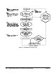


The Trigger Delay The trigger delay parameter allows you to specify the period between the
trigger signal and the measurement. For the stand-alone multimeter, this is
the delay between the trigger and the first measurement of each burst. For
the scanning multimeter, it’s the delay between the trigger and the first
channel in each scan (Figure 4-2).
Note that you can set the sample period between measurements in a burst
and the sample period between FET multiplexer channels with the
SAMPle:TIMer command.
The trigger delay is set with the commands:
TRIGger:DELay period | MIN | MAX
TRIGger:DELay:AUTO
mode
where:
period = period between the trigger signal and the measurement. The
range for period is 0 to 16.7772150 seconds.
MIN = sets the minimum trigger delay of 0 seconds for DC voltage and
resistance measurements. Sets a delay of 0.5 seconds for AC voltage
measurements.
MAX = sets the maximum trigger delay of 16.7772150 seconds.
mode =
ON; delay is 0 seconds for the DC voltage and resistance
measurements, 0.5 seconds for the AC voltage measurements. To reduce
the delay for AC voltage measurements, change the function to AC
voltage first, and then set the delay.
MEASure and CONFigure set
TRIGger:DELay:AUTO ON.
OFF turns TRIGger:DELay:AUTO off. Specifying a trigger delay
automatically turns
TRIG:DEL:AUTO off.
Figure 4-2. Multimeter Trigger Delays
106 Understanding the HP E1326B/E1411B Multimeter Chapter 4