
User`s manual

Agilent E1330B Digital I/O Module Register Information 113
Appendix B
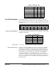
Port Transfer
Control Register
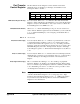
The Port Transfer Control Register controls transfers between the
mainframe and port, identifies port interrupts, and identifies forced
interrupts from the controller.
DRR (Data Register Ready) Is a read-only bit. When set to "1", it indicates either that the Port Data
Register contains valid data for the mainframe to read, or that the Port Data
Register is ready for the mainframe to write a byte of data to it. When the
Port Data Register is read, DRR is set to "0".
HE (Handshake Enable) When set to "1", enables handshaking for the port. You can read from or
write to this bit. When the registers have been initialized, you can set this bit
to "1" to enable handshaking if you are using the port handshake lines to
transfer data.
Bits 2 - 4 Are not used.
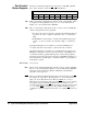
TI (Transfer Interrupt) Is a read-only bit. When set to "1", indicates a port transfer has occurred. A
port transfer interrupt, if enabled, occurs on a "port data register ready"
condition (when bit 0 of this register is set to "1"). To enable port transfer
interrupts, specify the "interrupt driven" transfer mode of port (refer to Port
Handshake Register) and set the "interrupt enable" bit (bit 7 of Interrupt
Control Register) equal to "1". When the Port Data Register is read, TI is set
to "0".
FI (Forced Interrupt) Is a read-only bit. When set to "1", indicates that a forced interrupt (from the
mainframe) has occurred. To force an interrupt, write a "1" to bit 6 and bit 7
of the Port Interrupt Control Register and bit 6 of the Status/Control
Register.
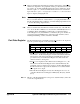
PI (Peripheral Interrupt) Bit 7 is a read/write bit. Writing a "1" to bit 7 enables port peripheral
interrupts. Writing a "0" disables port peripheral interrupts. When reading
bit 7, a "1" indicates a port interrupt has occurred. To clear PI you must write
a "0" to PI. Writing a "0" then a "1" to PI is the correct procedure to clear
one interrupt and re-enable for a second one.
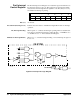
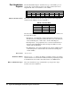
Note Port peripheral interrupts are caused by a transition in the PIR line. If bit 4
of the Port Normalization Register is "0", a rising-edge (low to high)
transition caused the interrupt. If bit 4 is set to "1", a falling-edge (high to
low) transition caused the interrupt. Refer to the Port Normalization
Register for more information.
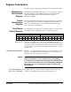
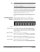
Port Address (0–3) base+0C
16
, base+0D
16
, base+0E
16
, base+0F
16
76543210
PI FI TI — — — HE DRR