
User`s manual

20 Configuring the Agilent E1330B Digital I/O
Chapter 2
Selecting the Interrupt Line
The VXI peripheral interrupt bus consists of seven lines which can carry the
interrupt signal to the commander. The most common line to be used is line
one, as this is the usual default interrupt line. Many VXIbus commanders
have a way to change the interrupt line they manage (for example, the
E1405/06 has an interrupt line allocation table). When doing direct
register-based programming, instead of using the SCPI driver, set the
interrupt line to a line that is not used by the SCPI driver. Module interrupt
priority can be established with these lines. In general, the higher the line
number, the higher the priority.
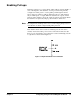
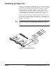
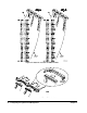
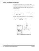
Referring to Figure 2-1, near the P1 connector you will find two sets of
jumper pins labeled X and 1 through 7 (JM15 and JM16). The Digital I/O
module is factory-shipped with the interrupt set to 1. If you need to change
the interrupt level you must move both jumpers on the blocks. Spare
jumpers, used for combining the flag (FLG) lines, are stored on the unused
ground pins of this connector when it ships from the factory.
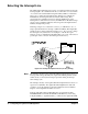
Note The interrupt circuitry for the Agilent E1330B is implemented as release on
interrupt acknowledge (ROAK). The Agilent E1330B Digital I/O module
will de-assert (or release) the interrupt request line during an interrupt
acknowledge cycle.
The interrupt circuitry on the Agilent E1330A is implemented as release on
register access (RORA). The Agilent E1330A Digital I/O module will
continue to assert the interrupt request line until the Port Control/Status
Register on the Digital I/O module is accessed.
Both the Agilent E1330A and E1330B can be used with the Agilent
E1300B/E1301B and with the E1405A/B and E1406A. If you are using
Compiled SCPI (i.e., Agilent E1570A), you must use the Agilent E1330B.
Figure 2-4. Priority Interrupt Connector (Factory Setting)