
User`s manual

Configuring the Agilent E1330B Digital I/O Module 25
Chapter 2
Configuring for Isolated Digital I/O
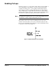
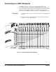
The two Digital I/O module peripheral connectors, J1 and J2, each have 60
pins. An industry standard isolated digital I/O peripheral, like the Opto 22
16 Position Single Channel Mounting Rack, is a 50-pin connection. The
connector is either a card edge or a header connector (similar to J1 on the
Digital I/O module). For example, the Opto 22
rack, PB16C, uses a card
edge connector; PB16H uses a header connector. They both have the same
pin-out for the ribbon cable. Both can accommodate up to 16 single channel
I/O lines.
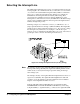
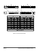
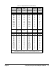
12 of the wires on the supplied ribbon cable are not connected. Figure 2-8
shows the ribbon cable connections. The method of connection to the ribbon
cable can be facilitated by the use of specialty fixtures for these connectors,
but there is no standard for connector keys or spacing.
For the Opto 22
rack, lines 1–10 are not used on the peripheral connector.
Pins 27–57 on the ribbon cable, odd numbered pins only, correspond to pins
17–47 on the Opto 22
rack. All even numbered pins are ground. Do not
connect pins 1 and 49 on the Opto 22
rack connector.
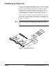
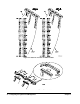
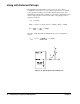
Procedure 1. Carefully cut lines 1-11 on the ribbon cable and line 59. A tan wire
should be the first wire on the ribbon cable after you make the cut.
2. Select the 50-pin connector you need, either edge connector or header
connector and attach the ribbon cable.
3. Connect the ribbon cable to the Opto 22
rack for optically isolated
digital operation.
Opto 22
is a registered trademark of Opto 22, Huntington Beach, CA 92649