
User`s manual


Understanding the Agilent E1330B Digital I/O Module 47
Chapter 4
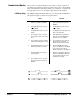
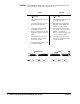
PULSe The PULSe handshake makes use of both the CTL and FLG lines. The input
and output operations are described below.
INPUT OUTPUT
1 The Digital I/O module senses the
FLG line and waits for READY.
1 The Digital I/O module checks the
state of the FLG line (must be
READY).
2 The Digital I/O module sets the
I/O
line HIGH.
2 The Digital I/O module sets the
I/O line LOW.
3 The Digital I/O module sets CTL
TRUE.
3 The Digital I/O module places the
data on the data lines.
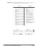
4 The peripheral senses the CTL
line and sets the FLG line to
BUSY.
4 After waiting the programmed
delay time, Td, the Digital I/O
module sets CTL to TRUE.
5 The peripheral places the data on
the data lines and indicates valid
data by setting the FLG line to
READY.
5 The Digital I/O module then waits
another delay time, Td, and sets
the CTL line to FALSE.
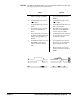
6 The Digital I/O module senses the
FLG READY, returns CTL to
FALSE, and latches the input
data.
6 The peripheral senses the CTL
line change, sets the FLG line to
BUSY and latches the data.
7 When the data is entered, the
peripheral returns the FLG line to
READY.