
Service manual


Performance Test Record
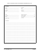
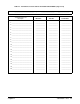
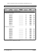
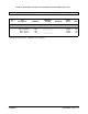
Table 2-1, "Performance Test Record for the E1364A Switch Module," is a
form you may copy and use to record performance verification test results
for the switch module. Pages 3 and 4 of Table 2-1 show switch accuracy,
measurement uncertainty (M.U.), and test accuracy ratio (TAR) values.
Switch Accuracy Accuracy is defined for closed-channel contact resistance and DC isolation
using the specifications in Appendix A of the E1364A User’s Manual. The
closed-channel resistance and DC isolation specifications are single-sided,
meaning that there is an upper limit OR a lower limit, but not both. In Table
2-1, either the "Minimum" or "Maximum" column will be blank for a
single-sided test.
Measurement
Uncertainty
For the performance verification tests in this manual, the measurement
uncertainties are based on 90-day accuracy specifications for the 3458A
Digital Multimeter. The calculations are shown below.
Closed-Channel
Resistance Test
Conditions:
– 4-wire ohms function
– 10 Ω range
– 90-day specifications
– Worst-case reading = 3.5 Ω
M.U. = 15ppm of Reading + 5ppm of Range
= 15 x 10
-6
⋅ 3.5 + 5 x 10
-6
⋅ 10 (Ω)
= 1.03 x 10
-4
Ω
DC Isolation Test Conditions:
– 2-wire ohms function
– 1 GΩ range
– 90-day specifications
– Worst-case reading = 1.2 GΩ (highest resistance that can be
measured with the 3458A)
M.U. = 0.5% of Reading + 10ppm of Range
= 0.005 ⋅ 1.2 x 10
9
+ 10 x 10
-6
⋅ 1 x 10
9
(Ω)
= 6 x 10
6
Ω
Test Accuracy
Ratio (TAR)
Test Accuracy Ratios are not defined for single-sided measurements, so all
closed-channel resistance and DC isolation measurements have "NA" (Not
Applicable) in the TAR column.
Chapter 2 Verification Tests 33