
User manual


Register-Based Programming 103Appendix B
Status/Control
Register
You can perform reads and writes to the Status/Control Register
(base + 04
16
). The following table defines the Status/Control Register bits.
Writing to the
Status/Control Register
Writes to the Status/Control Register (base + 04
16
) enable you to disable/
enable the interrupt generated when channels are closed. To disable the
interrupt generated when channels are closed, write a "1" to bit 6 of the
Status/Control Register (base + 04
16
). Typically, interrupts are only disabled
to "peek-poke" a module. See the operating manual of your command
module before disabling the interrupt.
Reading the
Status/Control Register
Each relay requires about 12 msec execution time during which time the
multiplexers are "busy". Bit 7 of this register is used to inform the user of
a "busy" condition. The interrupt generated after a channel has been closed
can be disabled. Bit 6 of this register is used to inform the user of the
interrupt status.
For example, if the Status Register (base + 04
16
) returns D3BF, the
multiplexer module is not busy (bit 7 set), the interrupt is enabled
(bit #6 = 0), and the configuration is four-wire (bits 10-13 set).
In addition, if a terminal module card is connected to the relay switch card,
the present configuration of the terminal module card’s status bit can be
read. Bits 10, 11, 12, and 13 are used to determine the configuration of
the terminal module card.
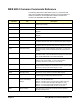
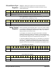
base + 04
16
15 14 13 12 11 10 9 8 7 6 5 4 3 2 1 0
Write* Undefined D Undefined
Read** Undefined S4 S3 S2 S1 Undefined B D Undefined
*D = Disable Interrupt by writing "1" in bit #6.
** B = Status "busy" is "0" in bit #7.
** D = Status "interrupt disable" is "1" in bit #6.
** S1-4 = Status "Configuration Status bits" as follows:
1-wire mode: bit #13 = 0, bit #12 = 0, bit #11 = 0, bit #10 = 1
2-wire dual 32 mode: bit #13 to 10 = all 0’s or all 1’s
2-wire 64 mode: bit #13 = 0, bit #12 = 0, bit #11 = 1, bit #10 = 0
3-wire mode: bit #13 = 0, bit #12 = 0, bit #11 = 1, bit #10 = 1
4-wire mode: bit #13 = 0, bit #12 = 1, bit #11 = 0, bit #10 = 0