
Graphics Tablet User Manual


11
Installing the Agilent E1438
To install the Agilent E1438
To protect circuits from static discharge, observe anti-static techniques whenever handling
the Agilent E1438 VXI ADC Module.
1. Set up your VXI mainframe. See the installation guide for your mainframe.
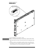
2. Select a slot in the VXI mainframe for the E1438 module.
The Agilent E1438D module’s local bus receives ECL-level data from the
module immediately to its left and outputs ECL-level data to the module
immediately to its right. Every module using the local bus is keyed to prevent
two modules from fitting next to each other unless they are compatible. If you
will be using the local bus, select adjacent slots immediately to the left of the
data-receiving module. If the VXI bus is used, maximum data rates will be
reduced but the module can be placed in any available slot.
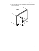
3. Using a small screwdriver or similar tool, set the logical address configura-
tion switch on the E1438. (See the illustration on the next page.) Each module
in the system must have a unique logical address. The factory default setting
is 1100 0000 (192).
For optimal phase noise performance in multi-module systems it is recommended that the first
channel be an Agilent E1438C or D. The Agilent E1438C does not support local bus or fiber optic
transfers.
Multi-module systems may include multiple Agilent E1438s or Agilent E1439s but not a mixture
of the two types of modules.