Agilent E361xA 60W BENCH SERIES DC POWER SUPPLIES OPERATING AND SERVICE MANUAL FOR MODELS: Agilent E3614A Agilent E3615A Agilent E3616A Agilent E3617A April 2000 Edition 8 Manual Part No.
SAFETY SUMMARY The following general safety precautions must be observed during all phases of operation, service, and repair of this instrument. Failure to comply with these precautions or with specific warnings elsewhere in this manual violates safety standards of design, manufacture, and intended use of the instrument. Agilent Technologies assumes no liability for the customer's failure to comply with these requirements. SAFETY SYMBOLS BEFORE APPLYING POWER.
Table of Contents SAFETY SUMMARY . . . . . . . . . . . . . . . . . . . . . . . . . . . . . . . . . . . . . . . . . . . . . . . . . . . . . . . . . . . . . . 1-2 GENERAL INFORMATION . . . . . . . . . . . . . . . . . . . . . . . . . . . . . . . . . . . . . . . . . . . . . . . . . . . . . . . . . 1-4 INTRODUCTION . . . . . . . . . . . . . . . . . . . . . . . . . . . . . . . . . . . . . . . . . . . . . . . . . . . . . . . . . . . . . . . . 1-4 SAFETY REQUIREMENTS . . . . . . . . . . . . . . . . . . . . . . . .
GENERAL INFORMATION OPTIONS Options 0EM, 0E3 and 0E9 determine which line voltage is selected at the factory. The standard unit is configured for 115 Vac ± 10%. For information about changing the line voltage setting, see paragraph "INPUT POWER REQUIREMENTS", page 1-6.
be grounded or the power supply can be operated floating at up to a maximum of 240 Volts off ground. Total output voltage to ground must not exceed 240 Vdc. LINE FUSE Line Voltage 100/115 Vac 230 Vac Fuse 2.0 AT 1.0 AT SPECIFICATIONS Detailed specifications for the power supply are given in Table 1. All specifications are at front terminals with a resistive load, and local sensing unless otherwise stated.
Table 1. Specifications and Operating Characteristics (Cont’d) *REMOTE PROGRAMMING SPEED DC ISOLATION Maximum time required for output voltage to change from initial value to within a tolerance band (0.1%) of the newly programmed value following the onset of a step change in the programming input voltage. Full load No load Up: E3614A: 3 msec 2 msec E3615A: 9 msec 6 msec 85 msec 85 msec E3616A: 200 msec 200 msec E3617A: Down: E3614A: 7 msec 1.6 sec 13 msec 2.2 sec E3615A: 65 msec 1.
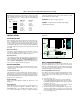
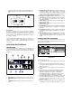
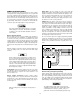
e. Replace the cover and mark the supply clearly with a tag or label indicating the correct line voltage and fuse that is in use. 4. DISPLAY OVP/CC SET Switch: Pressing this switch causes the VOLTS display to show voltage setting for overvoltage shutdown (trip voltage) and the AMPS display to show the current control set value. Setting values are either front panel settings or remote voltage programmed settings. 5.
that the current limit value can be set from zero to maximum rated value. False OVP shutdowns may occur if you set the OVP shutdown too close to the supply's operating voltage. Set the OVP shutdown voltage 4% of output +2.0 V or more above the output voltage to avoid false shutdowns from load-induced transients. OPERATING MODES The setting of the rear panel switch determines the operating modes of the power supply.
REMOTE OPERATING MODES Output Noise. Any noise picked up on the sense leads will appear at the supply's output voltage and may degrade CV load regulation. Twist the sense leads to minimize the pickup of external noise and run them parallel and close to the load leads. In noisy environments, it may be necessary to shield the sense leads. Ground the shield at the power supply end only. Do not use the shield as one of the sensing conductors.
MULTIPLE-SUPPLY OPERATION ply above 100% rated output. Limit your programming voltage to 10 Vdc. Normal parallel and auto-parallel operation provides increased output current while normal series and auto-series provides increased output voltage. Auto-tracking provides single control of output voltage of more than one supply. You can set up the unit for multiplesupply operation by changing the settings of the rear panel switch and connecting the leads from the rear panel terminals to the load.
Setting Voltage and Current. Turn the slave unit's CURRENT control fully clockwise. Adjust the master unit's controls to set the desired output voltage and current. The master supply operates in a completely normal fashion and may be set up for either constant voltage or constant current operation as required. Verify that the slave is in CV operation. gramming according to the remote-programming instructions.
AUTO-SERIES OPERATION above the master unit's current setting to avoid having the slave switch to CC operation. Auto-series operation permits equal or proportional voltage sharing, and allows control of output voltage from one master unit. The voltage of the slaves is determined by the setting of the front panel VOLTAGE control on the master and voltage divider resistor. The master unit must be the most positive supply of the series.
Remote Sensing. To remote sense with auto-series operation, set SENSE switch of the master unit and set SENSE switch of the slave unit to remote. Remote Analog Programming. To simultaneously remote program both units' output voltages, set up only the master unit for remote voltage programming according to the remote programming instructions. To vary the fraction of the output voltage contribution by the slave unit, connect a variable resistor in place of R2 in two units operation.
LOAD CONSIDERATIONS a. The output impedance of the power supply decreases with increasing frequency. b. The recovery time of the output voltage is longer for load resistance changes. c. A large surge current causing a high power dissipation in the load occurs when the load resistance is reduced rapidly. This section provides information on operating your supply with various types of loads connected to its output.
SERVICE INFORMATION Figure A-1. Block Diagram PRINCIPLES OF OPERATION The main secondary winding of the power transformer has three sections (N1, N2, and N3), each of which has a different turns ratio with respect to the primary winding. At the beginning of each half-cycle of the input ac, the control circuit determines whether one pair, both or none of the SCR will be fired.
series pass transistors. Whenever the output voltage is below the sloping V1 line, the control circuit inhibits four SCRs and the input capacitors charge to a voltage determined by N1. Figure A-2 indicates the windings that are connected as a result of the other voltage decisions. Full protection against any overload condition is inherent in the Constant Voltage/Constant Current design principle since there is not any load condition that can cause an output which lies outside the operating region.
Electronic Load. The test and calibration procedures use an electronic load to test the supply quickly and accurately. An electronic load is considerably easier to use than load resistor. It eliminates the need for connecting resistors or rheostats in parallel to handle the power, it is much more stable than carbon-pile load, and it makes easy work of switching between load conditions as is required for the load regulation and load transient response tests. a.
CONSTANT VOLTAGE (CV) TESTS Line Regulation (Source Effect) CV Setup. For all CV tests set the output current at full rated output to assure CV operation. The onset of constant current can cause a drop in output voltage, increased ripple, and other performance changes not properly ascribed to the constant voltage operation of the supply.
Figure A-5. Load Transient Response Time Waveform PARD(Ripple and Noise) Definition: PARD is the Periodic and Random Deviation of the dc output voltage from its average value, over a specified bandwidth and with all other parameters maintained constant. Constant voltage PARD is measured in the root-meansquare(rms) or peak-to-peak(pp) values over a 20 Hz to 20 MHz bandwidth. Fluctuations below the lower frequency limit are treated as drift.
CONSTANT CURRENT (CC) TESTS a. Connect the test equipment as shown in Figure A-7. b. Turn the supply's power on and turn CURRENT control fully clockwise. c. Turn up output voltage to the full rated value. Check that the supply's CV indicator remains lighted. Reduce VOLTAGE control if not lighted. d. Set the oscilloscope to AC mode and bandwidth to 20 MHz. e. Check that the peak-to-peak noise is less than 1 mV. CC Setup.
CC Drift (Stability) e. Record output voltage across Rs and convert it to current by dividing this voltage by Rs. f. Adjust autotransformer to the high line voltage (127 Vac for nominal 115 Vac, 110 Vac for nominal 100 Vac, and 253 Vac for nominal 230 Vac). g. When the reading settles, record the voltage across Rs again and convert it current. Check that the two recorded readings differ less than 0.01% of output current plus 250 µA.
Ammeter and CC Set Calibration Overall Troubleshooting Procedure To calibrate ammeter and CC set, proceed as follows: a. Connect test setup on Figure A-9. b. Turn VOLTAGE and CURRENT control fully clockwise. c. Turn on the supply and to calibrate ammeter adjust R5 on the display board until front panel AMPS display reads exactly DVM value divided by Rs. d.
After the trouble has been isolated to one of the feedback loops, troubleshooting can proceed as described in Tables A4, A-5, or A-6. series regulator backwards a stage at a time, since loop failures occur more often at the higher power levels. Preregulator Feedback Loop. The preregulator feedback loop (SCR control circuit) can be conveniently checked using Table A-6.
Table A-3. Overall Troubleshooting (Cont’d) SYMPTOM CHECKS AND PROBABLE CAUSES Poor Load Regulation (Constant Voltage) a. Refer to "Measurements Techniques" paragraph. b. Check +10 V reference voltage. c. Ensure that the supply is not going into current limit. Poor Load Regulation (Constant Current) a. Check +10 V reference voltage. b. CR1, CR19, CR20, C2, C31 leaky. c. Ensure that the supply is not crossing over to constant voltage operation. Oscillates (Constant Voltage/ Constant Current) a.
Table A-5. Low Output Voltage Troubleshooting (Cont’d) STEP ACTION RESPONSE PROBABLE CAUSE 4 Check voltage from pin 13 to pin 12 of U9. a. Measured voltage is positive. b. Measured voltage is negative. a. Check U9A is defective. b. Check U10 and U9D is defective. Check R85 is open. 5 Check voltage from pin 6 to pin 5 of U9. a. Measured voltage is positive. b. Measured voltage is negative. a. U9B is defective. b. Check U9C is defective. Table A-6.
Table A-7. Overvoltage Protection Circuit Troubleshooting STEP ACTION RESPONSE PROBABLE CAUSE 1 Short U19 pin 4 to TP6. a. Shutdown release (OVP indicator OFF) b. Output voltage remains shutdown(0 V) a. U20 defective or C57 shorted. b. Proceed to step 2. 2 Measure the voltage from TP6(common) to TP9. a. High voltage (+5 V) b. Low voltage (0 V) a. U19 defective or proceed step 3. b. U4D defective. 3 Measure the voltage from TP6(common) to TP8. a. Below +2.6 V b. Above +2.6 V a.
Table A-10. Replaceable Parts List Reference Designator R84,85 Agilen Part Number Q'ty Description Model Mfr. P/N Mfr.
Table A-10. Replaceable Parts List (Cont'd) Reference Designator Agilent Part Number Q'ty Description Model Mfr. P/N Mfr. Code C18,21,24,27 0160-7077 4 CAP-FXD .1UF +-10% 630V POLYE-FL 14,15 28480 C19,22 0160-4822 2 CAP-FXD 1000PF +-5% 100V CER COG 14,15 28480 C20,23 0180-3970 2 CAP-FXD 1UF +-20% 50V AL-ELECTLT 14,15 28480 C28 0160-6225 1 CAP-FXD 0.33UF +-10% 250V POLYE-MET ALL 28480 C29 0160-4832 1 CAP-FXD 0.
Table A-10. Replaceable Parts List (Cont'd) Reference Designator Agilent Part Number Q'ty Description Model Mfr. P/N Mfr. Code R24,26,27,37,38, 64,88,117,120 0757-0442 9 RESISTOR 10K +-1% .125W TF TC=0+-100 ALL 28480 R25,30,33 0698-8824 3 RESISTOR 562K +-1% .125W TF TC=0+-100 ALL 28480 R28,111 0698-3228 2 RESISTOR 49.9K +-1% .125W TF TC=0+-100 ALL 28480 R29,68,86,89,91, 92,95,96,99,114, 121 0698-3162 11 RESISTOR 46.4K +-1% .
Table A-10. Replaceable Parts List (Cont'd) Reference Designator Agilent Part Number Q'ty Description Model Mfr. P/N Mfr. Code R62 0698-8826 1 RESISTOR 825K +-1% .125W TF TC=0+-100 17 28480 R63 0698-8827 1 RESISTOR 1M +-1% .125W TF TC=0+-100 ALL 28480 R65 0757-0274 1 RESISTOR 1.21K +-1%.125W TF TC=0+-100 ALL 28480 R67 0757-0438 1 RESISTOR 5.11K +-1% .125W TF TC=0+-100 ALL R69 2100-4306 1 RESISTOR-TRMR 50K 10% TKF TOP-ADJ 25-T ALL R70 0698-3243 1 RESISTOR 178K +-1% .
Table A-10. Replaceable Parts List (Cont'd) Reference Designator Agilent Part Number Q'ty Description Model Mfr. P/N Mfr. Code R115 0757-0463 1 RESISTOR 82.5K +-1% .125W TF TC=0+-100 15 28480 R115 0757-0462 1 RESISTOR 75K +-1% .125W TF TC=0+-100 16 28480 R115 0757-0461 1 RESISTOR 68.1K +-1% .125W TF TC=0+-100 17 28480 R116 0698-4489 1 RESISTOR 28K +-1% .125W TF TC=0+-100 14 28480 R116 0698-3161 1 RESISTOR 38.3K +-1% .
Table A-10. Replaceable Parts List (Cont'd) Reference Designator Agilent Part Number Q'ty Description Model Mfr. P/N Mfr. Code CR21,22,23,24,25, 1901-0033 26,27,28,29,30 10 DIODE-GEN PRP 180V 200MA DO-35 ALL 1N645 27014 VR1,2,3 1902-0579 3 DIODE-ZNR 5.1V 5% PD=1W IR=10UA ALL 1N4733APL 04713 RT1,2 0837-0261 2 DIODE-VARISTOR ALL V275LA20A 34371 C67 0160-0263 1 CAP-FXD 0.
Table A-11. Component Value Model Component E3614A E3615A E3616A E3617A C2 1000UF 25V +-20% AL-ELECTLT 470UF 50V +-20% AL-ELECTLT 330UF 50V +-20% AL-ELECTLT 220UF 100V +-20% AL-ELECTLT C7,8 39000UF 25V +-20% AL-ELECTLT 12000UF 63V +-20% AL-ELECTLT 5600UF 100V +-20% AL-ELECTLT 2700UF 160V +-20% AL-ELECTLT C11,16,17,25,26 0.01UF 100V +-10% CER X7R 0.01UF 100V +-10% CER X7R C12 0.1UF 50V +-10% CER X7R 0.1UF 50V +-10% CER X7R C18,21,24,27 0.1UF 630V +-10% POLYE-FL 0.
Manual Supplement Supplement Agilent Part Number : 5959-5336, Edition 4 Supplement Print Date : 14 April, 2000 This supplement updates the following document: Agilent E361XA 60W Series Lab Bench DC Power Supplies Manual Agilent Part Number : 5959-5310 What is a manual supplement? A manual supplement keeps your manual up-to-date. The supplement, which consists of additional pages for your manual, is shipped with the manual that it updates. Additional pages have page numbers with a lower-case letter.
Voltage and Current Programming of the E3614A/15A/16A/ 17A with a Voltage and Current Source Remote analog voltage programming permits control of the regulated output voltage or current by means of a remotely varied voltage or current. The stability of the programming voltages directly affects the stability of the output. The voltage control or current control on the front panel are disabled during analog programming.
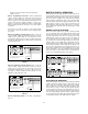
Programming Voltage Common to the Minus Output Figure 2 Set the CV switch down on the rear panel, and all others up. Vin = 1/A x Vout Vout = A x Vin Where Vout is the power supply output voltage. Vin is the programming voltage. A is the gain factor and the values of each model are as below. Model A 1/A E3614A 0.44 2.25 E3515A 0.67 1.5 E3616A 0.78 1.29 E3617A 0.86 1.
Programming Voltage Common to the Minus Output Figure 4 The output will always be the same or less than the programming voltage. The M/S2 switch must be in the down position. For best results, place a 0.1µF capacitor in parallel with R2. Vin = (R1 R2) / R2 x Vout Vout = R2 / R1+R2) x Vin Where Vout is the power supply output voltage. Vin is the programming voltage. R1 and R2 should be in the 1KΩ to 100KΩ range.
Constant Current Mode The E3614A/15A/16A/17A may be programmed for constant current with an analog voltage or current. Constant current with analog voltage programming can only be achieved with a voltage source that is common with the positive output terminal. Constant Current with Voltage Programming Figure 5 Set the CC switch down the rear panel, and all others up. Vin = 1/A x Iout Iout = A x Vin Where Iout is the power supply output current. Vin is the programming voltage.
Figure 6 Set the CC switch down, and all others up. Iin = 1/A x Iout Iout = A x Vin Where Iout is the power supply output current in amps. Iin is the programming current in µamps. A is the gain. A (A/µA) Model 1/A (µV/A) E3614A 0.055 18 E3515A 0.0278 35.9 E3616A 0.0158 63.4 E3617A 0.00928 108 Programming currents can be increased by adding a resistor across the CC+ and CC-. A 10 volts drop across R1 represents full scale current of the power supply.
Voltage and Current Programming of the E3614A/15A/16A/17A with Resistors Remote programming with resistors permits control of the regulated output or current by means of a remotely varied resistor. The sum of the resistance of external programming resistors (R1 + R2) should be more than 40 kohm. To have more precise output voltage, use a variable resistor more than 40 kohm. The voltage control on the front panel is disabled during remote resistor programming.
Remote Resistor Programming, Constant Current Figure 8 Set the CC switch down on the rear panel, and all others up. Iout = A x [VREF x {R/(R + R2 + 100)}] Where Iout is the power supply output current. A is the gain factor and the values of each model are as below. VREF is between 10.11 V and 11.40 V. R = (92800 x R1)/(92800 + R1) R1 + R2>> 40 kohm Model A E3614A 0.6 E3515A 0.3 E3616A 0.17 E3617A 0.
I CERTIFICATION Agilent Technologies certifies that this product met its published specifications at time of shipment from the factory. Agilent Technologies further certifies that its calibration measurements are traceable to the United States National Institute of Standards and Technology (formerly National Bureau of Standards), to the extent allowed by that organization's calibration facility, and to the calibration facilities of other International Standards Organization members.
DECLARATION OF CONFORMITY According to ISO/IEC Guide 22 and CEN/CENELEC EN 45014 Manufacturer’s Name: Manufacturer’s Address: Declares, that the product: Product Name: Agilent Technologies, Inc. Power Products PGU 140 Green Pond Road Rockaway, New Jersey 07866 U.S.