A Agilent E361xA 60W BENCH SERIES DC POWER SUPPLIES OPERATING AND SERVICE MANUAL FOR MODELS: Agilent E3614A Agilent E3615A Agilent E3616A Agilent E3617A For instruments with higher Serial Numbers than above, a change page may be included. Manual Part No.
A CERTIFICATION Agilent Technologies certifies that this product met its published specifications at time of shipment from the factory. Agilent Technologies further certifies that its calibration measurements are traceable to the United States National Institute of Standards and Technology (formerly National Bureau of Standards), to the extent allowed by that organization's calibration facility, and to the calibration facilities of other International Standards Organization members.
SAFETY SUMMARY The following general safety precautions must be observed during all phases of operation, service, and repair of this instrument. Failure to comply with these precautions or with specific warnings elsewhere in this manual violates safety standards of design, manufacture, and intended use of the instrument. Agilent Technologies assumes no liability for the customer's failure to comply with these requirements. SAFETY SYMBOLS BEFORE APPLYING POWER.
DECLARATION OF CONFORMITY The Declaration of Conformity (DoC) for this instrument is available on the Agilent website. You can search the DoC by its product model or description at the web address below. http://regulations.corporate.agilent.com/DoC/search.htm Note If you are unable to search for the respective DoC, please contact your local Agilent representative.
Table of Contents SAFETY SUMMARY . . . . . . . . . . . . . . . . . . . . . . . . . . . . . . . . . . . . . . . . . . . . . . . . . . . . . . . . . . . . . . 1-2 GENERAL INFORMATION . . . . . . . . . . . . . . . . . . . . . . . . . . . . . . . . . . . . . . . . . . . . . . . . . . . . . . . . . 1-4 INTRODUCTION . . . . . . . . . . . . . . . . . . . . . . . . . . . . . . . . . . . . . . . . . . . . . . . . . . . . . . . . . . . . . . . . 1-4 SAFETY REQUIREMENTS . . . . . . . . . . . . . . . . . . . . . . . .
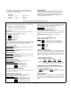
GENERAL INFORMATION OPTIONS Options 0EM, 0E3 and 0E9 determine which line voltage is selected at the factory. The standard unit is configured for 115 Vac ± 10%. For information about changing the line voltage setting, see paragraph "INPUT POWER REQUIREMENTS", page 1-6.
grounded or the power supply can be operated floating at up to a maximum of 240 Volts off ground. Total output voltage to ground must not exceed 240 Vdc. LINE FUSE Line Voltage 100/115 Vac 230 Vac Fuse 2.0 AT 1.0 AT SPECIFICATIONS Detailed specifications for the power supply are given in Table 1. All specifications are at front terminals with a resistive load, and local sensing unless otherwise stated.
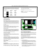
Table 1. Specifications and Operating Characteristics (Cont’d) *REMOTE PROGRAMMING SPEED DC ISOLATION Maximum time required for output voltage to change from initial value to within a tolerance band (0.1%) of the newly programmed value following the onset of a step change in the programming input voltage. Full load No load Up: E3614A: 3 msec 2 msec E3615A: 9 msec 6 msec E3616A: 85 msec 85 msec E3617A: 200 msec 200 msec Down: E3614A: 7 msec 1.6 sec E3615A: 13 msec 2.2 sec E3616A: 65 msec 1.
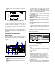
e. Replace the cover and mark the supply clearly with a tag or label indicating the correct line voltage and fuse that is in use. 4. DISPLAY OVP/CC SET Switch: Pressing this switch causes the VOLTS display to show voltage setting for overvoltage shutdown (trip voltage) and the AMPS display to show the current control set value. Setting values are either front panel settings or remote voltage programmed settings. 5.
that the current limit value can be set from zero to maximum rated value. False OVP shutdowns may occur if you set the OVP shutdown too close to the supply's operating voltage. Set the OVP shutdown voltage 4% of output +2.0 V or more above the output voltage to avoid false shutdowns from load-induced transients. OPERATING MODES The setting of the rear panel switch determines the operating modes of the power supply.
REMOTE OPERATING MODES leads. Ground the shield at the power supply end only. Do not use the shield as one of the sensing conductors. Remote operating modes discussed below are remote voltage sensing and remote voltage programming. You can set up the unit for remote operating modes by changing the settings of the rear panel switch and connecting the leads from the rear panel terminals to the load or the external voltage. Solid conductors of 0.75 Stability.
Remote Programming Connections. Remote programming requires changing settings of the switch and connecting external voltages to + and - terminals of "CV" or "CC" on the rear panel. Any noise picked up on the programming leads will appear on the supply's output and may degrade regulation. To reduce noise pick-up, use a twisted or shielded pair of wires for programming, with the shield grounded at one end only. Do not use the shield as a conductor.
Setting Voltage and Current. Turn the slave unit's CURRENT control fully clockwise. Adjust the master unit's controls to set the desired output voltage and current. The master supply operates in a completely normal fashion and may be set up for either constant voltage or constant current operation as required. Verify that the slave is in CV operation. gramming according to the remote-programming instructions.
AUTO-SERIES OPERATION above the master unit's current setting to avoid having the slave switch to CC operation. Auto-series operation permits equal or proportional voltage sharing, and allows control of output voltage from one master unit. The voltage of the slaves is determined by the setting of the front panel VOLTAGE control on the master and voltage divider resistor. The master unit must be the most positive supply of the series.
Remote Sensing. To remote sense with auto-series operation, set SENSE switch of the master unit and set SENSE switch of the slave unit to remote. Remote Analog Programming. To simultaneously remote program both units' output voltages, set up only the master unit for remote voltage programming according to the remote programming instructions. To vary the fraction of the output voltage contribution by the slave unit, connect a variable resistor in place of R2 in two units operation.
LOAD CONSIDERATIONS a. The output impedance of the power supply decreases with increasing frequency. b. The recovery time of the output voltage is longer for load resistance changes. c. A large surge current causing a high power dissipation in the load occurs when the load resistance is reduced rapidly. This section provides information on operating your supply with various types of loads connected to its output.
www.agilent.