
Installation guide

1-40
Agilent Technologies E5500B Installation Guide
Welcome to the E5500B Phase Noise Measurement System Series of
Solutions
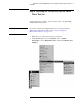
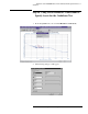
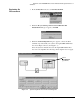
The appropriate measurement definition parameters for this example
have been pre-stored in this file. Table 1-4 on page 1-40 lists the
parameter data that has been entered for the Agilent/HP 70420A
Confidence Test example.
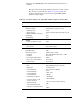
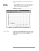
Table 1-4 Parameter Data for the Agilent/HP 70420A Confidence Test Example
Ste
p
Parameters Data
1 Type and Range Tab
Measurement Type
• Start Frequency
• Stop Frequency
• Minimum Number of Averages
FFT Quality
Swept Quality
• Baseband Noise (using a test set)
•10Hz
• 100E + 6 Hz (determined by analyzer used)
•4
•Fast
•Fast
2CalTab
• Gain preceding noise input • 0 dB
3 Block Diagram Tab
• Noise Source • Test Set Noise Input
4 Test Set Tab
Input Attenuation
LNA Low Pass Filter
•LNAGain
•DCBlock
• PLL Integrator Attenuation
• Ignore out-of-lock conditions
• Pulsed Carrier
•0dB
• 20 MHz (Auto checked)
• Auto Gain (Minimum Auto Gain - 14 dB)
• Not checked
•0dBm
• Not checked
• Not checked
5GraphTab
•Title
• Graph Type
• X Scale Minimum
• X Scale Maximum
• Y Scale Minimum
• Y Scale Maximum
• Normalize trace data to a:
• Scale trace data to a new
carrier frequency of
• Shift trace data by
• Trace Smoothing Amount
• Power present at input of DUT
• Agilent E5500 Phase Noise System
Confidence Test
• Base band noise (dBV/Hz)
•10Hz
•100E+6Hz
•0dBc/Hz
• - 200 dBc/Hz
• 1 Hz bandwidth
• 1 times the current carrier frequency
•0dB
•0
•0dBm