
Specifications


11
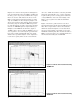
b) When the connect diagram is displayed, check
hardware and connections.
1) Connect scope to monitor port of 70420A
test set.
2) Set scope to monitor waveform.
3) Connect the signal paths to the phase noise
test set.
4) Set quadrature (set the signal to zero volts
on scope and a null on View Meter).
c) Select Continue.
d) When prompted by the software, connect the
calibration signal from the calibration source
to the coupler, then select Continue.
e) When prompted by the software, disconnect
the calibration signal from the calibration
source, then select Continue.
8. When the measurement is complete, print the
results and save the measurement file.
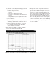
9. Interpret the results. A typical residual noise
floor measurement when using the microwave
phase detector is shown in Figure 2-8. The noise
level close to carrier is influenced by the AM
noise characteristics of the stimulus source (in
this case, the Agilent 83732B). The rise in the
noise level far from carrier (>40 MHz offset) is
due to the delay difference in the signal paths.
Since this configuration is intended for pulsed
carrier measurements, where data is valid only
to a PRF/2 offset frequency, this delay differ-
ence is acceptable.
Figure 2-8. CW residual noise floor using an Agilent 83732B as the stimulus source