
Specifications


13
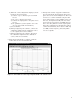
Example 2: Pulsed carrier noise floor using an
Agilent 83732B as the stimulus source
1. Connect the components as shown in Figure 2-9.
The amplifier after the pulse modulator may be
necessary to set the appropriate power levels at
the signal and reference inputs of the phase
noise measurement system. Do not connect the
signal paths to the phase noise measurement
system at this step.
2. Set up stimulus source.
a) Carrier frequency: 1.5 GHz
b) Amplitude: Set power levels at the connectors
to the 70420A detector input ports:
Ref Input: 10 dBm
Signal Input: 0 dBm
3. Set up pulse generator.
a) Duty Cycle = 10%
b) PRF = 20 kHz
c) Connect pulse generator output to the pulse
modulator.
4. Set up calibration source.
a) Carrier frequency: 1.500005000 GHz (5 kHz
offset from the stimulus source)
b) Amplitude: Set spur power level at the
70420A reference input port –40 dBc @ 5 kHz
from CW carrier
c) Disconnect calibration signal from coupler
Pulse
Gen
83732B
Stimulus
Source
Pulse
Modulator
Splitter
Attenuator
E5500
Input
Ref
Input
Phase
Shifter
16 dB Coupler
Amplifier
8663A
Calibration
Source
Figure 2-9. Connection diagram for pulsed carrier residual phase noise
measurement