
Specifications


16
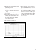
Figures 2-11 and 2-12 show pulsed residual phase
noise measurements where the PRF is 20 kHz and
the duty cycle is 10 percent, but different low-pass
filters are used to demonstrate the effects of the
PRF—even though measurement results are valid
only out to PRF/2 in offset frequency. Figure 2-11
shows a broad offset range pulsed carrier measure-
ment using only the default 100-MHz low-pass fil-
ter and allowing the system to autorange the LNA.
Note the 20 kHz PRF spurious signal and integer
multiples of the PRF. The break in the graph at
10 MHz is due to the fact that the PRF lines are too
close together to be resolved by the spectrum ana-
lyzer (the resolution bandwidth and video band-
width of the spectrum analyzer can be adjusted to
resolve these spurs). There is also a break in the
curve at a 1 kHz offset. This is caused by the LNA
gain being automatically set to a lower gain than
required. (The presence of large phase transients
or large PRF lines causes the autoranging of the
LNA to select a gain lower than the maximum
available.)
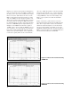
Figure 2-12 shows a pulsed carrier noise floor
measurement using the internal 200 kHz low-pass
filter. The low-pass filter reduces the transients
within the baseband signal to a level that allows
the proper autoranging of the LNA (to select the
maximum available gain). The measured results to
PRF/2 of offset frequency are virtually identical to
the measurement using the 20 kHz LPF.
Figure 2-11. Pulsed carrier measurement using
100 MHz LPF
Figure 2-12. Pulsed carrier measurement using
200 kHz LPF