
Specifications


29
5. Set up the phase noise measurement system.
a) From the Define menu, choose Measurement;
then define the measurement per the parame-
ter data provided in Table 3-4. When all of
the forms have been defined, choose the
Close button.
b) For this configuration, the 10-MHz reference
oscillator within the down converter will be
tuned to achieve measurement phase-lock.
The internal PLL loops of the downconverter
restrict the acceptable closed-loop measure-
ment bandwidth to <<126 Hz. With an open-
loop PTR of 75 Hz, this narrow closed-loop
bandwidth is achieved by selecting 12 dB of
PLL integrator attenuation (located on Test
Set definition page).
6. Start New Measurement.
a) Select New Measurement from the Measure
pulldown menu.
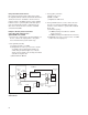
b) When the connect diagram is displayed, check
hardware and connections.
1) Connect scope to monitor port of 70420A
test set.
2) Set scope to monitor waveform.
3) Connect the signal paths to the phase noise
test set.
4) Verify that a beat note exists within the RF
pulse “ON” time.