
Specifications


32
This chapter includes the recommended hardware
configurations and step-by-step measurement pro-
cedures for making AM noise measurements on
pulsed carriers.
Measurement considerations
Using an external AM detector:
1) Choose a low-barrier Schottky diode detector, if
possible, since these detectors will handle more
power than a point-contact detector, while being
just as sensitive.
2) Terminate the diode with an external AM detec-
tor filter (70429A k21). This network prevents
the DC voltage component of the demodulated
signal from saturating the LNA within the
70420A test set. It also sets the detector DC
bias and allows the minimum offset frequency
to be 1 Hz.
3) Provide an external PRF filter if the internal
70420A low-pass filters do not provide sufficient
PRF filtering for a successful measurement.
4) Provide a coaxial balun (70427A k02) between
the detector and the test set to help eliminate
ground loop spurious signals and noise.
Using an internal AM detector:
The 70420A test set with Option 001 provides an
internal AM detector to measure AM noise between
10 Hz and 100 MHz of offset range. The test set
also provides an internal DC block that limits the
minimum offset frequency to 10 Hz.
The 70427A microwave downconverter also pro-
vides an AM detector that can be used to measure
the AM noise of a signal over the offset range of
1 Hz to 100 MHz when an external DC block is
used. The output of the AM detector (within the
70427A downconverter) is routed externally to
the 70420A’s External Noise Input port.
PRF filtering
Internal low-pass filters are available to provide
PRF filtering for some situations. Because the AM
detector produces a high-amplitude replica of the
carrier pulse, the PRF filter must have more atten-
uation than the PRF filter used in the phase noise
measurement case. An internal low-pass filter can
be used if the cutoff frequency is one-half of the
PRF or less.
Unless the PRF happens to be one half the cutoff
frequency of one of the internal low pass filters,
the offset range will be limited by the filter to less
than PRF/2. The available internal filters are
shown in Table 4-1.
4. Making AM noise measurements on pulsed carriers
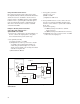
Figure 4-1. Pulsed carrier AM noise measurement configuration when using an external AM detector
70429A k21
E5500
70427A k02
Noise
Input
Ref
Input
16 dB Coupler
Calibration
Source
Detector
Filter
PRF
LPF
Coax
Balun
33330C
Source
"DUT"
Pulse
Modulator
83732B
External Pulse Input
AM Detector