
Specifications


33
Table 4-1. Selecting an Internal Low-Pass Filter for
AM Noise Measurements
PRF LNA Low-Pass Filter
≥40 kHz 20 kHz
≥400 kHz 200 kHz
≥4 MHz 2 MHz
≥40 MHz 20 MHz
However, if the PRF frequency is the same as
the low-pass filter, an external PRF filter and AM
detector may be required. PRF lines are AM in
nature and they will appear at the LNA at full
magnitude if PRF filtering does not reduce them
sufficiently.
Measurement calibration
The easiest and most appropriate calibration
method for pulsed carrier AM noise measurements
is the “Single-Sided Spur Calibration Technique.”
This technique is described in the Agilent E5500
series user documentation. The method is the same
for pulsed carrier conditions as CW conditions,
with the caution that the calibration sidebands
must be <PRF/4.
Example 1: Agilent 83732B pulsed AM noise measurement
using the internal AM detector
In this configuration, the internal AM detector of
the 70420A Option 001 test set will be used. The
optimal input power to the AM detector is +12 to
+15 dBm. The test set has an internal DC block
that is automatically used when the internal AM
detector is selected. This internal DC block may
also be used with an external AM detector, but the
minimum offset frequency will be limited to 10 Hz.
1. Connect the components as shown in Figure 4-2.
Do not connect the signal path to the phase
noise measurement system at this step.
2. Set up the DUT (83732B).
a) Carrier frequency: 1.5 GHz.
b) Amplitude: Set power level for a +12-dBm
signal at the 70420A signal input port.
c) External Pulse Enable
3. Set up the pulse generator.
a) Duty Cycle = 10%
b) PRF = 40 kHz
c) Amplitude = required pulse levels for the
source
4. Set up the calibration source.
a) Carrier frequency: 1.500005000 GHz
b) Amplitude: Set the calibration signal power
level at the 70420A reference input port to:
–40 dBc @ 5 kHz from CW carrier.
c) Disconnect calibration signal from coupler.
5. Set up the AM noise measurement system.
a) From the Define menu, choose Measurement;
then define the measurement per the param-
eter data provided in Table 4-2 (page 35).
When all of the forms have been defined,
choose the Close button.
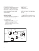
Figure 4-2. AM noise measurement configuration using the Agilent 70420A with
Option 001 (internal AM detector)
E5500
Input
AM Detector
16 dB Coupler
Source
"DUT"
Pulse
Modulator
83732B
External
Pulse Input
Pulse
Modulator