
Specifications


9
Step-by-step procedure
The following step-by-step procedure can be used
when making pulsed residual measurements with
any Agilent E5500 series phase noise measurement
solution. Modifications will be required for differ-
ent carrier frequencies, duty cycles, PRF, source
types, and so forth. Three measurement examples
using the same basic procedure are given: 1) a
noise floor measurement for a non-pulsed carrier
signal; 2) a noise floor measurement for a pulsed
carrier signal; and 3) a DUT measurement.
Example 1: Residual noise floor using an Agilent 83732B
as the source (non-pulsed carrier)
While this measurement uses a non-pulsed carrier
signal, the actual measurement configuration will
be the same as the configuration for a pulsed carrier
signal. The resulting noise floor measurement will
then incorporate all of the components used in the
pulsed carrier situation. It is possible to predict
the pulsed carrier noise floor from the non-pulsed
carrier noise floor if the duty cycle of the pulsed
signal is known.
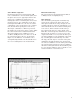
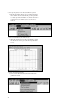
1. Connect the components as shown in Figure 2-7.
The amplifier after the pulse modulator may be
necessary to set the appropriate power levels
at the signal and reference inputs of the phase
noise measurement system. Do not connect the
signal paths to the phase noise measurement
system at this step.
2. Set up the stimulus source.
a) Carrier frequency: 1.5 GHz
b) Amplitude: Set power levels at the connections
to the 70420A detector input ports:
Ref Input: 7 to 10 dBm
Signal Input: 0 to 5 dBm
3. Set up the pulse generator and pulse modulator.
a) Duty Cycle = CW (100%)
b) PRF = None
c) Amplitude = TTL Output
4. Set up the calibration source.
a) Carrier frequency: 1.500005000 GHz
b) Amplitude: Set spur power level at the
70420A reference input port to –40 dBc @
5 kHz from CW carrier
c) Disconnect calibration signal from coupler
Figure 2-7. Connection diagram for residual noise floor measurement
Pulse
Gen
83732B
Stimulus
Source
Pulse
Modulator
Splitter
Attenuator
E5500
Input
Ref
Input
Phase
Shifter
16 dB Coupler
Amplifier
8663A
Calibration
Source