
User`s guide


Additional Imaging Modes 7
Agilent 5500 SPM User’s Guide 133
amplitude exceeding 10 V, beyond which the signal will be
clipped. The default value is x1 (the amplitude times 1).
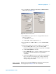
e Select the EFM Tune check box.
f In the AC Mode Tune window, set the Start and End frequencies
for the EFM tune sweep. Use a wide range centered on the
Lock-in 2 frequency.
g Click the Manual Tune button. The system will sweep Lock-in 2
through the range of frequencies, displaying any peak oscillation
amplitude within the range.
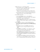
h Adjust the Frequency in the EFM tab if it falls close to one of
these peak frequencies.
i In the Servo window return the Setpoint to its original value.
13 On the EFM tab clear the EFM Tune check box.
14 On the EFM Controls Main tab, click the Zero Phase button to set
the phase at the current frequency to zero, making it easier to
interpret phase changes from the current value.
15 On the EFM tab, click Optimize Phase. This will shift the phase of
the Lock-in 2 signal to maximize the X component of phase.
16 In the Servo window set the I Gain and P Gain to 5 %. These gains
dictate how quickly the system will react to changes in amplitude.
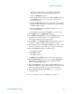
17 In the Scan and Motor window’s Scan tab, enter:
a Scan Speed of 1-2 ln/s.
b Resolution of 256.
c Scan Size (in microns).
d X Offset and/or Y Offset values to set the center of the scan.
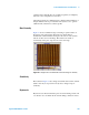
18 In the Realtime Images window, choose to display Topography
and Aux 1 (the X component of the phase signal which will be
mapped to make the EFM image).
19 In the Scan and Motor window, click the Up or Down blue arrow to
initiate a scan. The Aux 1 map will show changes in the electrostatic
force as they differ from the force at the touch-down location.
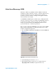
20 Adjust the Gain, Scan Speed, Resolution, etc., to optimize the
topography image.
For more on advanced options for EFM Mode see Chapter 11.